
Apparatus for rapidly correcting installation position of panoramic vision measuring system

A measurement system and installation location technology, applied in the direction of measurement devices, optical devices, instruments, etc., can solve problems such as calibration errors, and achieve high-precision correction, high practical value, and good adaptability.

Inactive Publication Date: 2011-06-01
HARBIN ENG UNIV
View PDF4 Cites 25 Cited by
  • Summary
  • Abstract
  • Description
  • Claims
  • Application Information

AI Technical Summary

Problems solved by technology

The above calibration methods are all based on the premise of the central catadioptric system or the assumption that the system satisfies the single-view constraint model. If the relationship between the mirror and the camera in the system does not satisfy the assumption, it will inevitably lead to calibration errors.

Method used


Image

  • Apparatus for rapidly correcting installation position of panoramic vision measuring system
  • Apparatus for rapidly correcting installation position of panoramic vision measuring system
  • Apparatus for rapidly correcting installation position of panoramic vision measuring system

Examples


Embodiment Construction

[0012] The present invention is described in more detail below in conjunction with accompanying drawing example:

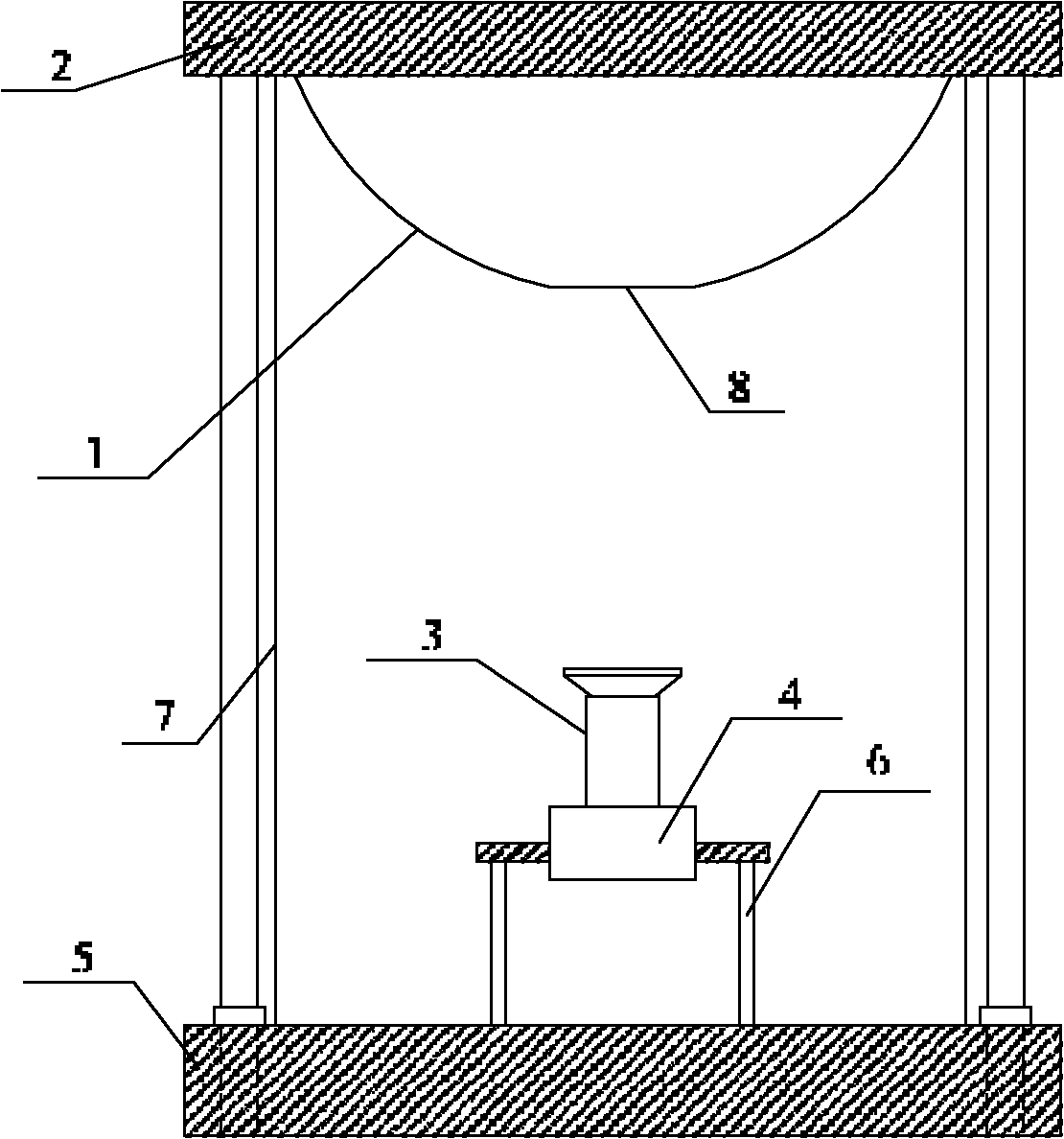
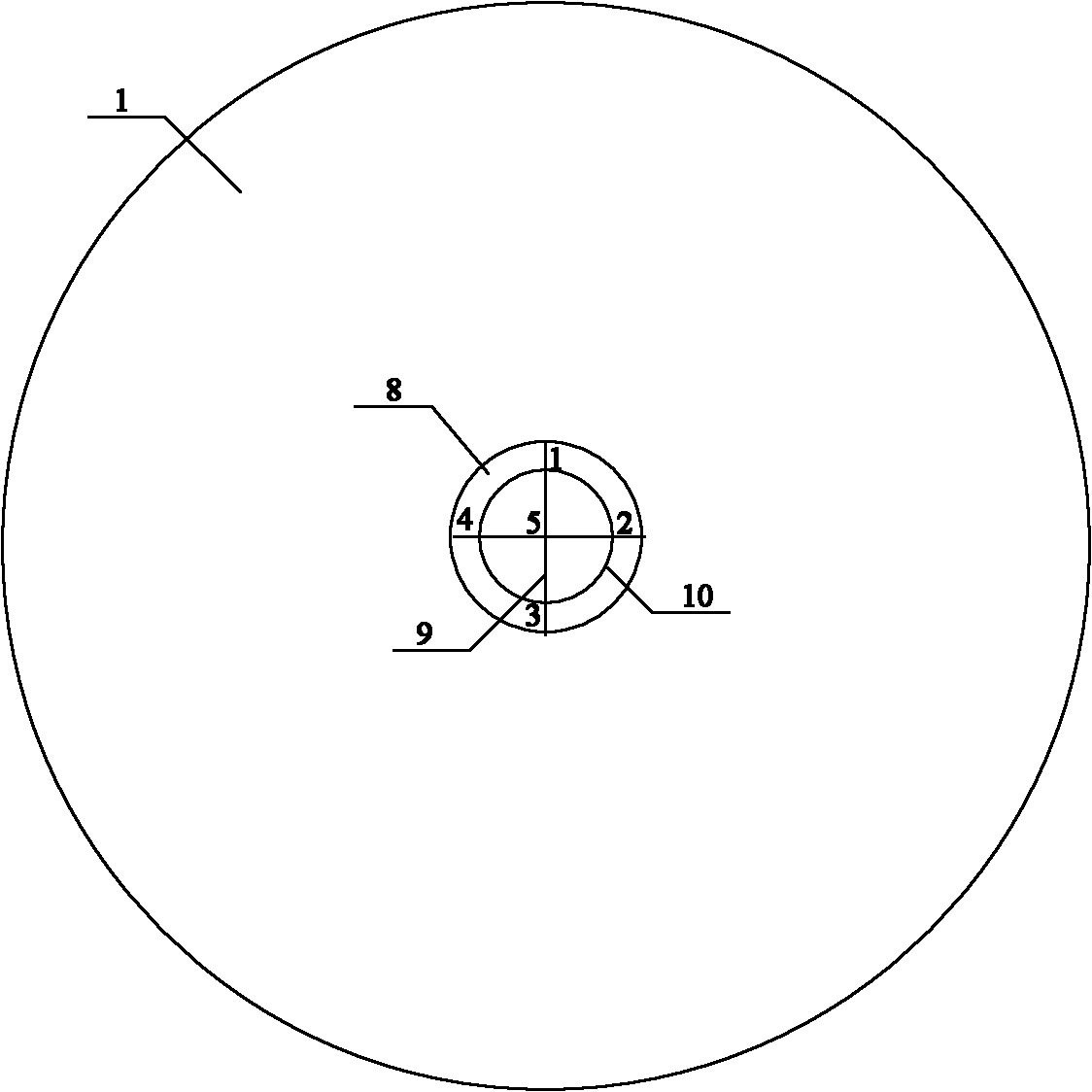
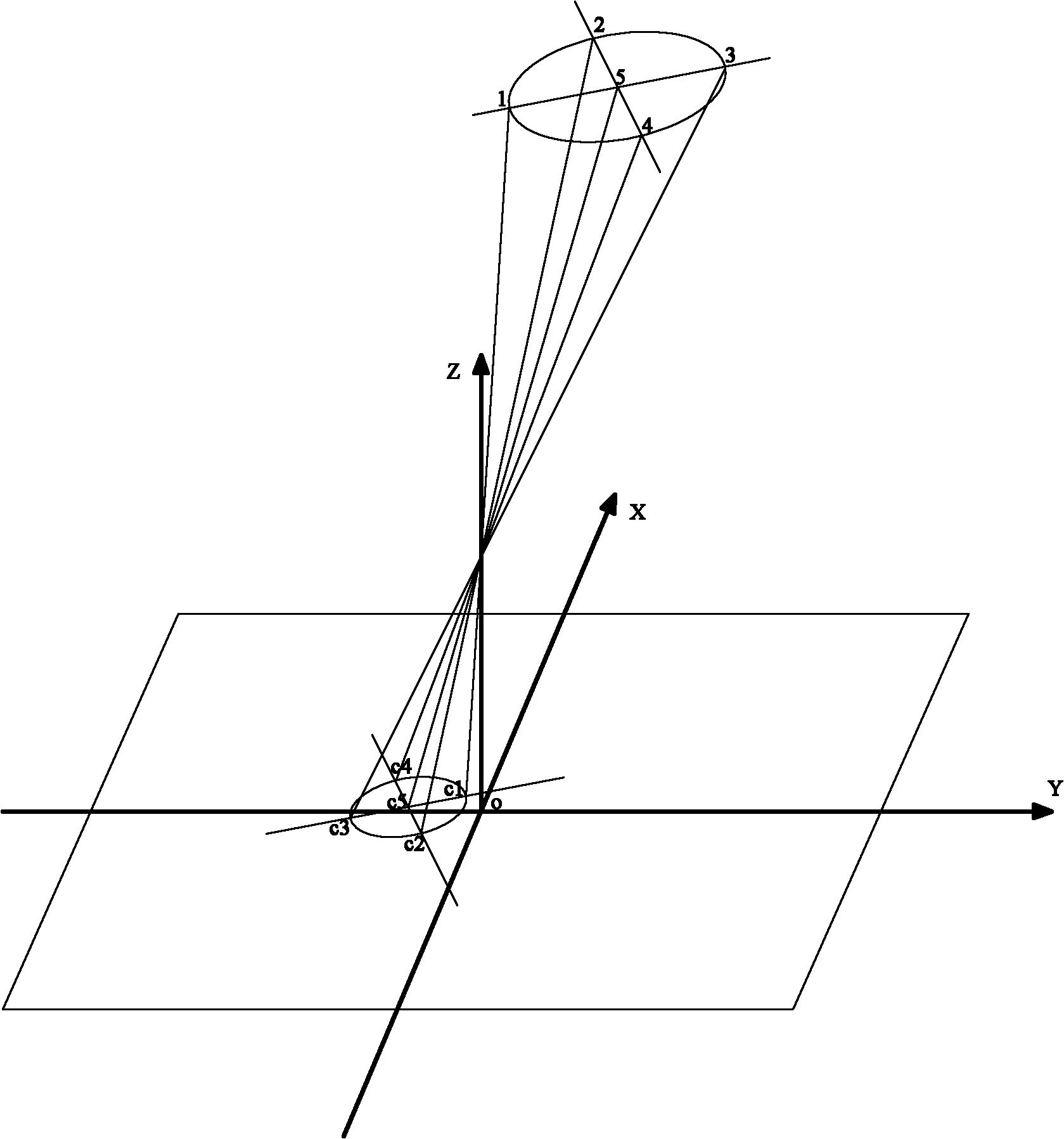
[0013] to combine figure 1 and figure 2 . The panoramic vision measurement system is equipped with a position correction device, including three parts: a viewfinder module, a perspective imaging module, and a protection module. Mirror connector 2; the perspective imaging module includes a high frame rate scientific grade camera 4 and a perspective lens 3; the protection module includes a protective glass tube 7. The viewing module is connected to the protective module through the connector 2, and the perspective imaging module is installed in the protective module through the bracket 6. The top of the hyperboloid reflector 1 is a circular plane 8, the center of which is the original vertex of the hyperboloid reflector 1, and the circular plane 8 is parallel to the bottom surface of the hyperboloid reflector 1. Marked on the circular plane 8 are a crossed reti...


PUM


Abstract

The invention provides an apparatus for rapidly correcting an installation position of a panoramic vision measuring system. The apparatus comprises a viewing module, a perspective imaging module and a protection module, wherein the viewing module comprises a hyperboloid reflector installed in a protective glass tube and a hyperboloid reflector connector arranged on the top of the protective glass tube; the perspective imaging module comprises a scientific grade camera with a high frame frequency, and a perspective lens; and the protective module comprises a protective glass tube. The viewing module is connected with the protection module through a connector; the perspective imaging module is installed in the protection module by a support; and the top of the hyperboloid reflector is a circular plane whose center is the original summit of the hyperboloid reflector, wherein the circular plane is in parallel with the bottom of the hyperboloid reflector. The apparatus provided by the invention has a simple structure and a good adaptability and needs no external auxiliary measures; the apparatus can realize high-precision correction of the installation position of the panoramic vision measuring system, therefore possessing a high practical value.

Description

technical field [0001] The invention relates to a test device, in particular to a device for correcting the installation position of a panoramic vision measurement system. Background technique [0002] Catadioptric panoramic vision can be traced back to 1970, when Dr. ReeS of the United States proposed for the first time in his patent the use of a hyperboloid mirror to achieve panoramic imaging. The advantage of the hyperboloid panoramic vision system is that it has a single projection center, and the vertical viewing angle can reach (-90°-45°). The panoramic image can be transformed into an ordinary perspective image and a cylindrical image; the perspective lens is the most commonly used one. Imaging lenses are mature in technology, diverse in variety, and flexible in selection, and if the curvature of the selected mirror is small, astigmatism can be reduced. The emergence of the panoramic vision system has promoted the development of a series of related theoretical resear...

Claims


Application Information

Patent Timeline
IPC IPC(8): G01C25/00G01B11/26G01B11/00
Inventor 朱齐丹夏桂华蔡成涛张智刘志林邓超姜迈
Owner HARBIN ENG UNIV
Learn More