Engagement arrangement

A technology for jointing devices and jointing components, which is applied in the direction of workpiece clamping devices, vises, manufacturing tools, etc., and can solve the problems of reduced effectiveness of MR fluid control

Inactive Publication Date: 2011-06-01
UNIVERSITY OF NOTTINGHAM
View PDF5 Cites 13 Cited by
  • Summary
  • Abstract
  • Description
  • Claims
  • Application Information

AI Technical Summary

Problems solved by technology

If these particles settle, the effectiveness of coagul

Method used


Image

  • Engagement arrangement
  • Engagement arrangement
  • Engagement arrangement

Examples


Embodiment Construction

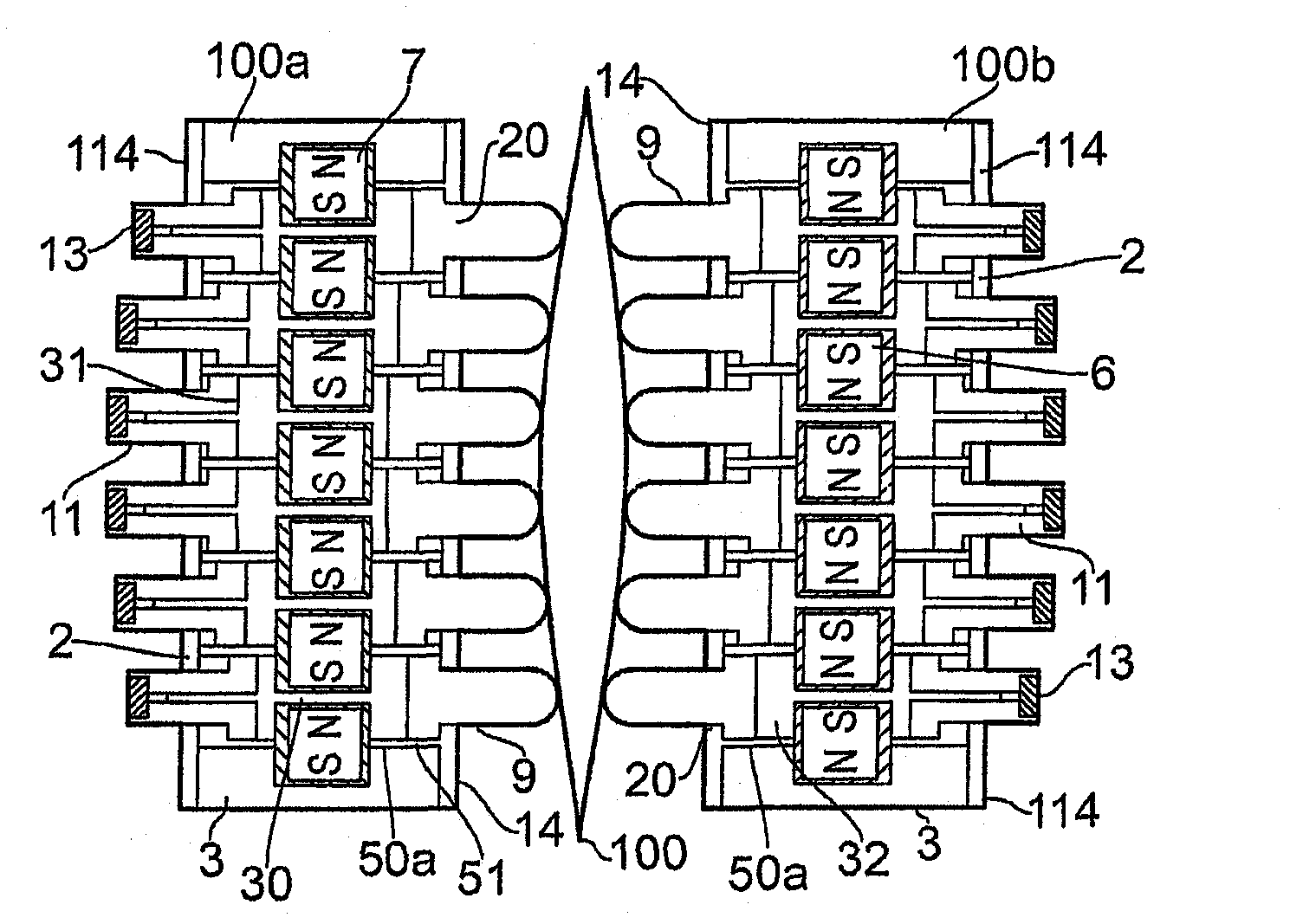
[0038] As noted above, reconfigurable properties are required to provide engagement means that allow the retention and gripping of members and assume a variety of regular or irregular shapes. According to aspects of the invention, the reconfigurable properties are achieved by using known magnetorheological fluids and referred to as MR fluids. Such MR fluids are well known for their properties and generally comprise a suspension of magnetically inducible particles which, under the influence of a magnetic field, acquire a near-solid viscosity in use. In this case, the fluid can transition between a fluid state and a substantially solid state. This capability is useful in a variety of contexts and, for aspects of the present invention, allows the fluid state of a device to be adjusted for engagement to a component and then maintained in that engaged position by converting the MR fluid or part of the fluid to a solid state. It will be appreciated that once initial contact and ret...


PUM

PropertyMeasurementUnit
Densityaaaaaaaaaa
Viscosityaaaaaaaaaa
Densityaaaaaaaaaa

Abstract

Retention of position and clamping of components is ideally performed with an engagement arrangement which is reconfigurabie. Magnetorheological (MR) fluids have been utilised for reconfigurabie engagement arrangements but typically require powerful electromagnets to activate the MR fluid. By providing enclosed chambers with a constriction in the form of a passage (30) between a reservoir portion (31) of the chamber and an engagement portion (32) of the chamber it is possible to utilise smaller permanent magnets (7) acting upon a smaller volume of MR fluid in the passage. In such circumstances initial positioning of engagement elements (9) is provided through forced displacement in the form of a plunger or pin (11) and then retention of the engagement element position achieved through positioning a magnetic field across and about a passage (30) to create an effective block retaining MR fluid volume and therefore presentation of the engagement element (9). In order to achieve such performance MR fluids which have an appropriate performance and durability are necessary. In such circumstances in accordance with other aspects of the present invention particular magnetorheological fluids are also described.

Description

technical field [0001] The present invention relates to contour engaging devices, and more particularly to engaging devices for gripping or retaining regularly or irregularly shaped members. Background technique [0002] It should be appreciated that in a wide range of engineering and other contexts it is desirable to grip or hold components such as airfoils to allow machining and other processes. Such members may be regularly shaped or irregularly shaped, but either way it is desirable to ensure correct position and orientation. It should be appreciated that components must be held and positioned precisely in such assemblies without damage to the components themselves, and to ensure that machining or other forming processes do not cause vibration or other movement that could cause the components to error handling. It will also be appreciated that in some cases, components may be held in a device such as a vise, allowing not only machining but also assembly of other compon...

Claims


Application Information

Patent Timeline
IPC IPC(8): B25B1/24B25B11/00
CPCB25B11/002B25B1/2457B25B1/2421
Inventor N·金迪A·法米Y·王V·S·坎查拉K·沃克
Owner UNIVERSITY OF NOTTINGHAM
Why Eureka
Try Eureka