
Pneumatic tire

A technology of pneumatic tires and tires, applied in tire parts, tire tread/tread pattern, rolling resistance optimization, etc., can solve problems such as inability to ensure braking performance, and ensure wear resistance and sufficient braking performance. , the effect of improving drainage

Inactive Publication Date: 2011-06-08
BRIDGESTONE CORP
View PDF1 Cites 7 Cited by
  • Summary
  • Abstract
  • Description
  • Claims
  • Application Information

AI Technical Summary

Problems solved by technology

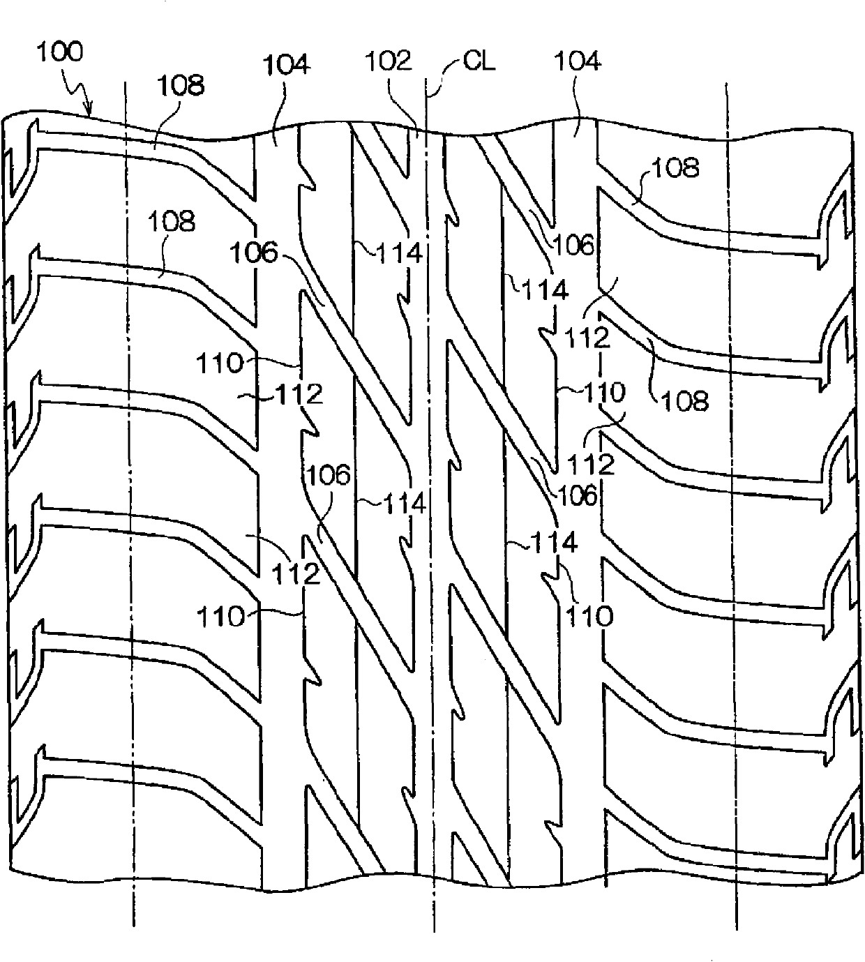
[0004]However, when a pneumatic tire with grooves arranged as described above is on a dry road surface, friction between the road surface and the edge portion of the block on the side of the lug groove Rolled up, there is a problem that sufficient braking performance cannot be secured
In addition, on wet and slippery roads with a small coefficient of friction, although the edges of the blocks on the side of the lug grooves effectively function to ensure a certain degree of braking performance, the braking performance on wet and slippery roads is also limited. Market demand for further improvement

Method used


Image

  • Pneumatic tire
  • Pneumatic tire
  • Pneumatic tire

Examples


Embodiment approach

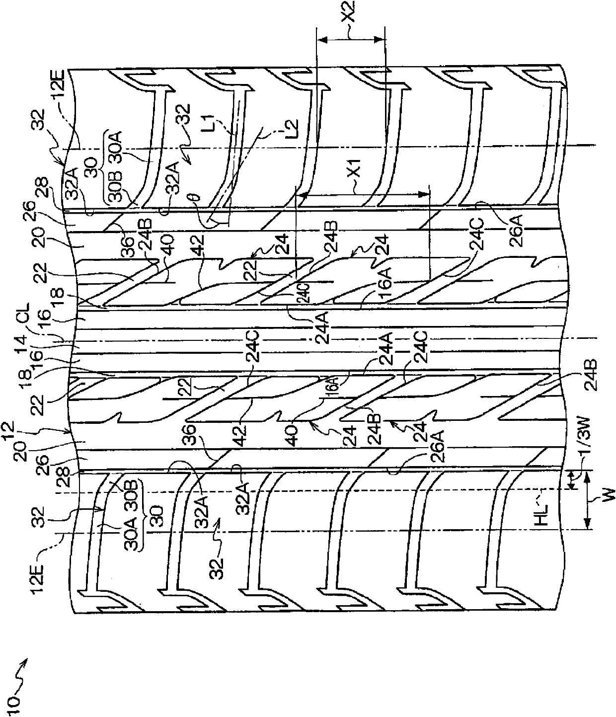
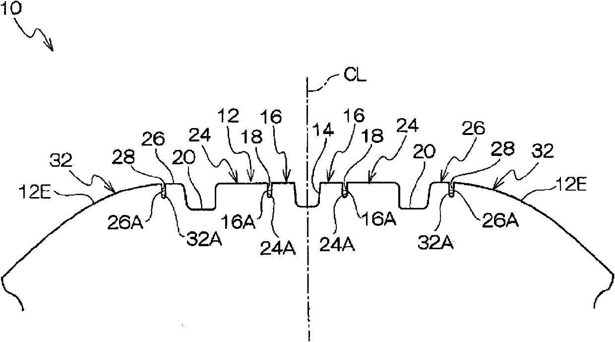
[0046] In the first embodiment, the tire circumferentially extending portion of the second sipe 42 formed on the center block 24 is on the same straight line as the first sipe 40 , but the present invention is not necessarily limited to In this structure, the first sipe 40 and the second sipe 42 may be shifted in the tire width direction, or a structure in which a plurality of first sipes 40 are formed on the center block 24 may be used.

[0047] In the above-mentioned embodiment, the first sipe 40 and the second sipe 42 have the same depth structure, but the present invention is not necessarily limited to this structure, and the first sipe 40 and the second sipe 42 may have the same depth. 42 is not the same depth.

[0048] In the above-mentioned embodiment, the first sipe 40 and the second sipe 42 are formed on the center block 24. However, the present invention is not necessarily limited to this structure. The first sipe 40 and the second sipe 42 are formed on the block 32...


PUM


Abstract

A tire having sufficient braking performance on a dry road and a wet road, having reduced rolling resistance, and having improved wear resistance performance. A tire (10) has a tread (12) provided with the following: center ribs (16) defined by a first circumferential groove (14) and by first narrow grooves (18) having groove walls making contact with each other when the tread (12) is compressed and deformed by engaging the ground; center blocks (24) defined, on the outer side of each first narrow groove (18) in the tire's lateral direction, by a second circumferential groove (20) and by center lug grooves (22) extending from the first narrow groove (18) to the second circumferential groove (20); first sipes (40) each formed in the surface of each center block (24) and each extending in the tire's circumferential direction from a wall surface (24B) toward a wall surface (24C) to terminate in the center block; and second sipes (42) each formed in the surface of each center block (24) and each extending in the tire's circumferential direction from the wall surface (24C) toward the wall surface (24B), bent in the middle, open to a wall surface (24A), and not intersecting with the first sipe (40) in a plan view. The tire (10) has sufficient braking performance on a dry road and a wet road, has reduced rolling resistance, and has improved wear resistance performance.

Description

technical field [0001] The invention relates to a pneumatic tire, in particular to a pneumatic tire for passenger cars. Background technique [0002] In conventional pneumatic tires, in order to ensure braking performance by utilizing the edge effect, a plurality of blocks are divided by forming circumferential grooves extending in the circumferential direction and lateral grooves extending approximately in the width direction on the tread surface. Such a method (for example, refer to Patent Document 1). [0003] Patent Document 1: Japanese Patent Application Laid-Open No. 09-328003 [0004] However, in a pneumatic tire having grooves arranged as described above, there is a problem that the edge portion of the block on the lug groove side is rolled up due to friction with the road surface on a dry road surface, and sufficient braking performance cannot be ensured. In addition, on wet and slippery roads with a small coefficient of friction, although the edges on the side of...

Claims


Application Information

Patent Timeline
Patent Type & Authority Applications(China)
IPC IPC(8): B60C11/04B60C11/01B60C11/11B60C11/12
CPCB60C11/12B60C2011/0348B60C11/0302B60C2011/0395B60C11/0306B60C2011/0393B60C2011/0374Y02T10/86B60C11/11B60C11/04B60C11/01
Inventor 中村贵光
Owner BRIDGESTONE CORP
Learn More