Circuit arrangement and method for operating at least one LED

A technology of light-emitting diodes and circuit devices, which is applied in the field of circuit devices and can solve problems such as low-quality projection results

Inactive Publication Date: 2011-06-08
OSRAM GMBH
View PDF4 Cites 2 Cited by
  • Summary
  • Abstract
  • Description
  • Claims
  • Application Information

AI Technical Summary

Problems solved by technology

This leads to lower quality projection results

Method used


Image

  • Circuit arrangement and method for operating at least one LED
  • Circuit arrangement and method for operating at least one LED
  • Circuit arrangement and method for operating at least one LED

Examples


Embodiment Construction

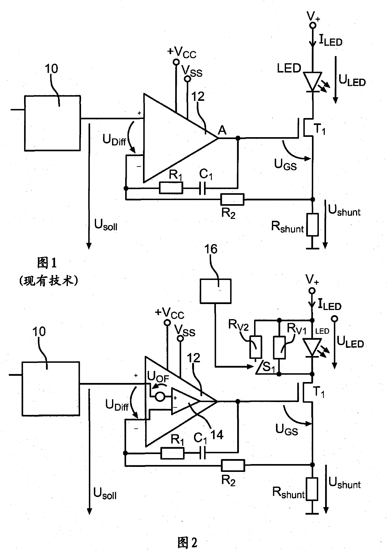
[0022] The reference numerals introduced with reference to FIG. 1 apply correspondingly to figure 2 The same or similar devices of the embodiments of the invention shown in . It was not reintroduced.

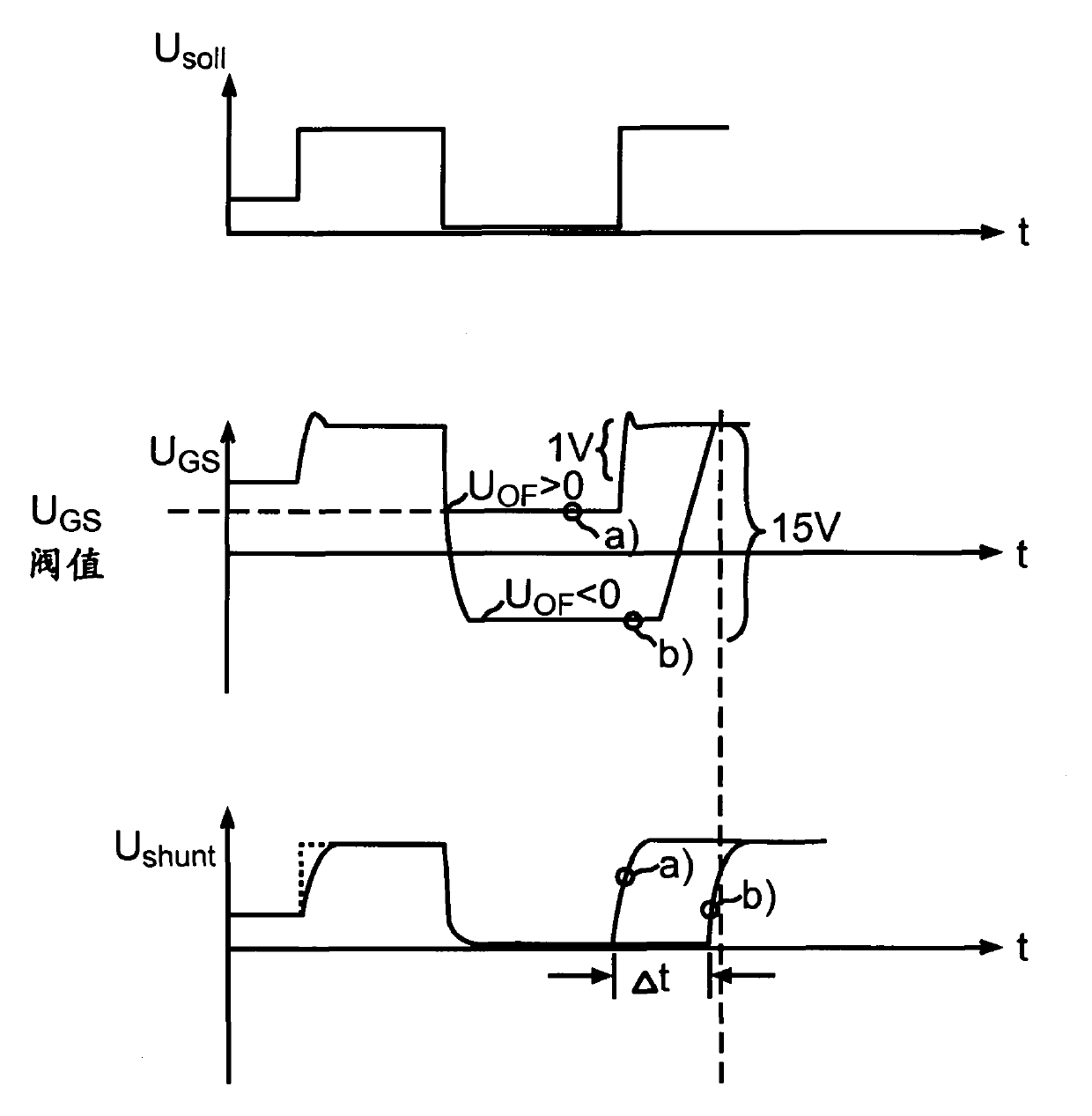
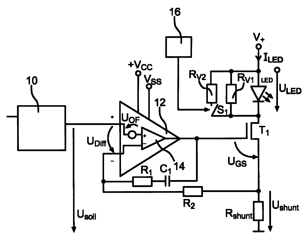
[0023] exist figure 2 The operational amplifier 12 is shown in detail in . In particular, a voltage source U is drawn between the positive input of operational amplifier 12 and the positive input of ideal operational amplifier 14 comprised in operational amplifier 12 OF , which reflects the so-called bias voltage. According to the production batch or aging state or other parameters, the bias voltage U OF Can be positive or negative. Irrelevant is that the difference voltage U between the positive and negative inputs of the operational amplifier 12 Diff is positive, that is, the bias voltage U OF is positive. Therefore, when the current I LED close to zero, the current measuring resistor R shunt The drop voltage U shunt Almost zero, but positive. A small positive vo...


PUM


Abstract

The present invention relates to a circuit arrangement for operating at least one LED, having an operational amplifier (12) with a non-inverting input and an inverting input as well as an output; a desired value predefining apparatus (10) which is coupled to the non-inverting input of the operational amplifier (12); a first connection and a second connection for the at least one LED, wherein the first connection is coupled to a connection for a DC supply voltage (V+); a transistor (T1) which is coupled in series with the first and second connections for the at least one LED and can be operated in an analogue manner, wherein the transistor (T1) has a control electrode, a reference electrode and a working electrode, wherein the control electrode of the transistor is coupled to the output ofthe operational amplifier (12), wherein the working electrode of the transistor (T1) is coupled to the connection for a DC supply voltage (V+); and a current measuring resistor (RShunt) which is coupled in series between the reference electrode of the transistor (T1) and a reference potential, wherein the voltage dropped across the current measuring resistor is coupled to the inverting input of the operational amplifier (12); wherein at least one load (RV1) is coupled in parallel with the first and second connections for the at least one LED. The invention also relates to a corresponding method for operating at least one LED.

Description

technical field [0001] The invention relates to a circuit arrangement for driving at least one light-emitting diode (LED), comprising: an operational amplifier with a positive and negative input and an output; a desired value predetermining device coupled to the positive input of the operational amplifier ; a first terminal and a second terminal for the at least one LED, wherein the first terminal is coupled to a terminal for a DC supply voltage; coupled in series with the first terminal and the second terminal for the at least one LED A transistor capable of being drivable in an analog manner, wherein the transistor has a control electrode, a reference electrode and a working electrode, wherein the control electrode of the transistor is coupled to the output of an operational amplifier, and wherein the working electrode of the transistor is coupled to a terminal for a DC supply voltage and a current-measuring resistor coupled in series between the reference electrode of the t...

Claims


Application Information

Patent Timeline
Patent Type & Authority Applications(China)
IPC IPC(8): H05B33/08H05B44/00
CPCH05B33/0818H05B45/37H05B45/397Y02B20/30
Inventor 拉尔夫·希英彼得·尼德迈尔奥斯卡·沙尔莫泽
Owner OSRAM GMBH
Why Eureka
Try Eureka