Positive light advertising board device

A billboard and positive light technology, applied in display devices, light guides, optics, etc., can solve the problems that the size and shape cannot meet the lively advertising lighting, the uniformity of the light source is difficult to control, and the light utilization efficiency is low, so as to increase added value and avoid The effect of glare afterglow and low stray light

Inactive Publication Date: 2010-06-16
秦厚敬
0 Cites 3 Cited by

AI-Extracted Technical Summary

Problems solved by technology

Generally speaking, the light utilization efficiency of the backlight type lighting is low, about 10~20%. The uniformity of the large-size surfa...

Method used

Described linear light source 1 makes light coupling enter in light guide plate 2 (referring to Fig. 1), and reflective sticker 4 reflects light back in light guide plate 2 to improve light utilization rate; The light of the total reflection angle condition (see Figure 2) is filled in the light guide plate 2 and cannot be separated, forming a necessary condition for the uniform illumination of the present invention; when the transparent bump 5 touches the surface of the light guide plate 2, the condition of total reflection optics changes , part of the LED light will penetrate through the contacted transparent bumps 5 and irradiate the objects outside the light guide plate 2 (see FIG. 2 ), such as the advertisement drawing 6 . A plurality of tiny transparent bumps 5 can be arranged on the surface of the advertisement drawing 6 or the light guide plate 2 by using the technique of screen printing. If the shapes and sizes of the transparent bumps 5 are similar, that is, their optical boundary conditions are similar, and the amount of light derived from a single transparent bump 5 is very similar in terms of the same area. The overall illumination design of advertising drawings will be converted into a simple scalar function relationship between large areas, and the illumination design with characteristics such as general uniformity, gradient grayscale change or color luster can be obtained without the simulation of complex optical program vectors ( See Figure 3). By setting the size (screen number) and density (DPI) of a plurality of tiny transparent bumps 5, it is possible to determine the required illuminance for designing advertising effects, which is a feature of the present invention. The invention utilizes screen printing technology to make precise patterns of 120dpi bumps on the drawings, that is, the distance between the light spots is 0.22mm, which is far smaller than the size of LED products in the industry. The invention is obvious in terms of cost, manufacturing, maintenance, and content expression It is superior to array-type LED products; moreover, advertising printing inks also provide richer colors. The light inside the light guide plate 2 is completely guided to the front of the advertising drawing 6 through the transparent bumps 5, and is conveyed to the eyes of the viewer with a large number of light spots and rich colors. Continuous reflection inside the light guide plate 2, so there is no stray light when watching the picture of the present invention. Screen printing designs with different densities can produce different lighting effects such as uniformity and grayscale. A low-cost advertising drawing 6 has different effects after turning on the active lighting and non-active lighting, which can express a dynamic appeal. For example, it can be Screen-print the company phone number or slogan, etc. on a white background with transparent bumps 5, and you will not know their existence under external lighting; but when the night is dark, after turning on the light source for active lighting, the transparent bumps 5 will turn into luminous bright spots. The white background becomes dark due to the lack of light illumination. This double dynamic effect is another major feature of the present invention. In addition, it is easy to mass-produce, construct, and replace advertising printing objects.
Referring to Fig. 5, the present invention can be applied to enhance the light transmittance of the LCD panel as a whole, only part of the unit pixel 50 is specifically permeable, called pixel opening 51, and the remaining part is the signal line 52 driven by the back , black frame, TFT driver assembly 53, wherein the ratio of the pixel opening 51 to the unit ...

Abstract

The invention discloses a positive light advertising board device, which comprises a light guide plate and an advertising board. At least one end face of the light guide plate is provided with a luminous source, the light guide plate is in gapless contact connection with the surface of the advertising board through a transparent salient point, the total reflection light in the light guide plate is guided to the front surface of the advertising board through the transparent salient point, and the position of the transparent salient point is at a light emission port in the light guide plate. The device is directly contacted with the advertising board in a mode of a light guide point, and can have multi-point precise selective illumination so as to reduce the loss of interface light, reduce the stray light, increase the white-black contrast, improve the optical efficiency and reduce the manufacturing and using costs. The advertising board is replaced by a common advertising board, and the device also can be used as an indoor common illumination lamp such as a desk lamp, a wall lamp and the like.

Application Domain

Technology Topic

PhysicsStray light +7

Image

  • Positive light advertising board device
  • Positive light advertising board device
  • Positive light advertising board device

Examples

  • Experimental program(2)

Example Embodiment

[0025] Example 1
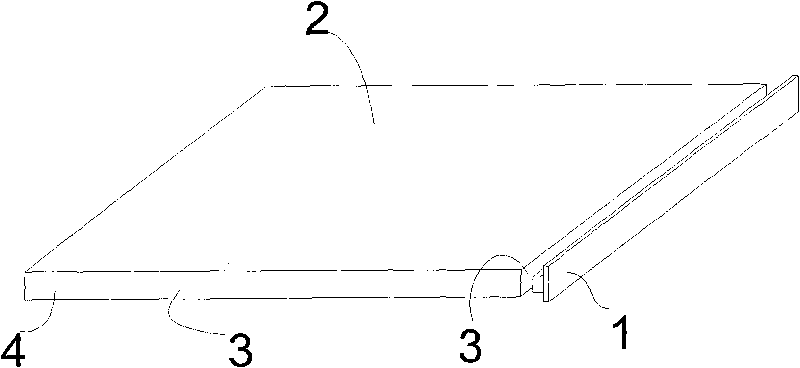
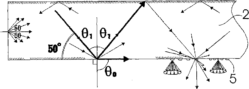
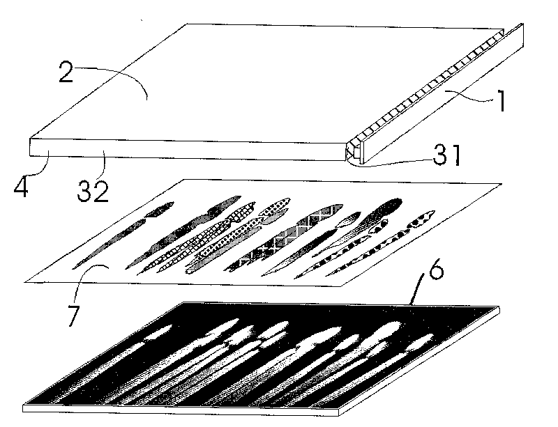
[0026] refer to figure 1 , 2 , 3. This embodiment includes a linear light source 1, a light guide plate 2, and the light guide plate 2 connects to the advertising drawing 6 through the surface of the transparent bump 5 without gaps; On the front of 6, the position of the transparent bump 5 is the outlet of the light in the light guide plate 2, and the distribution coating 7 of the transparent bump matches the content pattern of the advertisement drawing 6, producing a partially emphasized lighting effect.
[0027] The distribution, dot pitch, and height of the transparent bumps 5 can be varied depending on the artist's desired display effect, and there is no specific limitation.
[0028] One end surface 31 of the light guide plate 2 is provided with a linear light source 1, and the other end surface 32 is covered with reflective stickers 4; the linear light source 1 is formed by an arrangement of LED light sources (but not limited thereto).
[0029] The linear light source 1 couples the light into the light guide plate 2 (see figure 1 ), the reflective sticker 4 reflects the light back into the light guide plate 2 to improve the light utilization rate; after the LED light is reflected countless times, it meets the total reflection angle condition (see figure 2 ) light is filled in the light guide plate 2 and cannot be separated, forming a necessary condition for the uniform illumination of the present invention; when the transparent bump 5 touches the surface of the light guide plate 2, the conditions of total reflection optics will change, and part of the LED light will penetrate The object that touches the transparent bump 5 and irradiates the outside of the light guide plate 2 (see figure 2 ), such as advertising drawing 6. A plurality of tiny transparent bumps 5 can be arranged on the surface of the advertisement drawing 6 or the light guide plate 2 by using the technique of screen printing. If the shapes and sizes of the transparent bumps 5 are similar, that is, their optical boundary conditions are similar, and the amount of light derived from a single transparent bump 5 is very similar in terms of the same area. The overall illumination design of advertising drawings will be converted into a simple scalar function relationship between large areas, and the illumination design with characteristics such as general uniformity, gradient grayscale change or color luster can be obtained without the simulation of complex optical program vectors ( see image 3 ). By setting the size (screen number) and density (DPI) of a plurality of tiny transparent bumps 5, it is possible to determine the required illuminance for designing advertising effects, which is a feature of the present invention. The invention utilizes screen printing technology to make precise patterns of 120dpi bumps on the drawings, that is, the distance between the light spots is 0.22mm, which is far smaller than the size of LED products in the industry. The invention is obvious in terms of cost, manufacturing, maintenance, and content expression It is superior to array-type LED products; moreover, advertising printing inks also provide richer colors. The light inside the light guide plate 2 is completely guided to the front of the advertising drawing 6 through the transparent bumps 5, and is conveyed to the eyes of the viewer with a large number of light spots and rich colors. Continuous reflection inside the light guide plate 2, so there is no stray light when watching the picture of the present invention. Screen printing designs with different densities can produce different lighting effects such as uniformity and grayscale. A low-cost advertising drawing 6 has different effects after turning on the active lighting and non-active lighting, which can express a dynamic appeal. For example, it can be Screen-print the company phone number or slogan, etc. on a white background with transparent bumps 5, and you will not know their existence under external lighting; but when the night is dark, after turning on the light source for active lighting, the transparent bumps 5 will turn into luminous bright spots. The white background becomes dark due to the lack of light illumination. This double dynamic effect is another major feature of the present invention. In addition, it is easy to mass-produce, construct, and replace advertising printing objects.

Example Embodiment

[0030] Example 2
[0031] refer to Figure 4 , this embodiment includes a light guide plate 2, a reflective LCD panel 10, and the transparent bump coating 11 is a macroscopic presentation of the fine transparent bumps printed on the light guide plate 2, with a gradient effect in which the center is dense and gradually loosens around, The linear light source 1 injected laterally can be compensated to form a uniform LED positive light plate 20 , and then positively contact the reflective LCD panel 10 to form an LCD billboard 30 illuminated by LED positive light.
[0032] Transparent bump coating 11, wherein the pitch of the transparent bumps in the central area of ​​the light guide plate 2 is set to 0.15mm, then a better visual effect can be obtained, and the pitch of the transparent bumps in the edge area of ​​the light guide plate 2 is set to 0.30mm, transparent The attenuation of the side light source can be compensated by a simple and gradual distribution of the convex points, so as to obtain a uniform and soft positive light illumination suitable for reading at a close distance.
[0033] Each end surface of the light guide plate 2 is provided with a linear light source 1; the linear light source 1 is formed by an arrangement of LED light sources (but not limited thereto).
[0034] The present invention utilizes a linear light source 1 formed by arranging multiple LED light sources (but not limited thereto), and injects the light emitted by it into the end surface 3 of the light guide plate 2 (see Figure 4 ), the light is continuously reflected in the light guide plate 2, and the light meeting the total reflection condition fills the light guide plate 2 and cannot penetrate to the outside. By planning the distribution of micro-transparent bumps through the characteristics of the optical simulation light source, that is, the linear light source 1 and the light guide plate 2, a very uniform light distribution can be obtained. For example, the distribution density of the transparent bumps on the screen 11 decreases from the central area to the edge area, or the number of dots is adjusted, that is, the duty ratio of black and white in the dots, and the dot output from 1% to 100% duty ratio can be easily set. , to compensate for the attenuation of the light from the light source 1 due to the partial absorption of the transparent bumps with distance.
[0035] The LED light source irradiates the reflective LCD panel 10 in a contact manner, so that all the light is injected into the reflective LCD panel 10 without leakage, so the utilization efficiency of the light is improved, and the stray light is reduced; The liquid crystal layer (Liquid Crystal) in the LCD, the light will penetrate the liquid crystal layer for the first time and be reflected, and then pass through the liquid crystal layer for the second time before entering the eyes of the viewer. For positive lighting reflective LCD panels, on the path of light entering and exiting, all optical components will enter and exit twice, such as liquid crystal layer, color filter surface, polarizing layer, etc. The double shielding effect makes positive lighting LCD more efficient than backlight The black-and-white contrast of the image produced by the illuminated LCD is nearly squared.
[0036] refer to Figure 5 , the present invention can be applied to improve the light transmittance of the LCD panel as a whole. Only part of the unit pixel 50 is specifically light-transmittable, called the pixel opening 51, and the remaining part is the signal line 52, black frame, and TFT driver of the back drive. Component 53, wherein the ratio of the pixel opening 51 to the unit area of ​​the pixel is called the aperture ratio, and the aperture ratio in high-resolution LCDs is only about 60% to 70%. The manufacturing technology of micro lenses (MICRO LENS), such as ultraviolet curing glue (UV curing glue) Cooperate with the baking program of the curvature of the mirror surface, make the miniature transparent bumps 5 on the surface layer of the LCD panel 10, and the miniature transparent bumps 5 are correspondingly arranged at the pixel (pixel element) opening 51, and the LCD panel Each pixel center of 10 forms a 1-1 corresponding relationship, then the light in the light guide plate passes through the transparent bump 5, and the percentage of the light entering the opening 51 will be greatly increased, which can improve related circuits and isolation when making LCD pixels. The shadowing problem associated with the space can improve the luminous flux efficiency of the LCD. The technology of microlens (MICRO LENS) has been widely used in the production of CMOS and CCD sensors to increase the sensitivity of low light, but it is used in the illumination of positive LCD or electronic paper, in addition to increasing the brightness, it can also reduce stray light and increase contrast. The burden of vision when reading is of great development value.
[0037] If the transparent bump 5 and its contact surface are made of polarized material, the light that does not pass through the polarized material will be reflected back into the light guide plate 2 for continued recycling. Under the use of positive lighting, the LCD panel will be more simple and efficient than the existing backlighting.

PUM

PropertyMeasurementUnit
Height50.0µm
tensileMPa
Particle sizePa
strength10

Description & Claims & Application Information

We can also present the details of the Description, Claims and Application information to help users get a comprehensive understanding of the technical details of the patent, such as background art, summary of invention, brief description of drawings, description of embodiments, and other original content. On the other hand, users can also determine the specific scope of protection of the technology through the list of claims; as well as understand the changes in the life cycle of the technology with the presentation of the patent timeline. Login to view more.

Similar technology patents

Liquid crystal composition and liquid crystal display device thereof

PendingCN114196422AImprove transmittanceGood contrastLiquid crystal compositionsNon-linear opticsDielectric anisotropyHigh transmittance
Owner:JIANGSU HECHENG DISPLAY TECHCO

Method for selecting image data source in optical instrument

Owner:江苏钜芯集成电路技术股份有限公司

Liquid crystal compound and liquid crystal composition containing same, and liquid crystal display device

PendingCN113528152AWide Nematic Temperature RangeGood contrastLiquid crystal compositionsOrganic chemistryDielectric anisotropyRotational viscosity
Owner:JIANGSU HECHENG ADVANCED MATERIALS

Contrast Dyes for Inkjet Lithographic Printing Plates

InactiveUS20090036638A1Good contrastAzo dye preparationMonoazo dyesCarbon atomPhotochemistry
Owner:AGFA NV

Classification and recommendation of technical efficacy words

  • Good contrast

Double-frequency laser interferometry apparatus

InactiveCN101413783AAvoid frequency aliasingGood contrastUsing optical meansOptical pathOpto electronic
Owner:BEIJING CHANGCHENG METERING TEST TECH INST NO 1 GRP CO CHINA AVIATION IND

Liquid Crystal Display Device

InactiveUS20120242925A1Good contrastIncrease in costNon-linear opticsImage contrastLiquid-crystal display
Owner:JAPAN DISPLAY INC

Optical compensator for liquid crystal display

ActiveUS20050190327A1Good contrastPolarising elementsTemporary pavingsChemistryLiquid-crystal display
Owner:INNOLUX CORP
Why Eureka
Try Eureka