End traction and bolster positioning and clamping mechanism for chassis centered tyre

A technology for positioning, clamping and chassis, applied in metal processing, metal processing equipment, manufacturing tools, etc., can solve the problem of affecting the assembly efficiency of steel structure chassis components, the inconsistency of design benchmarks and process benchmarks, and affecting the installation of bolsters and other components Accuracy and other issues, to achieve good market prospects, simple and reliable structure, and reasonable positioning methods.

Active Publication Date: 2011-06-15
CRRC NANJING PUZHEN CO LTD
View PDF5 Cites 9 Cited by
  • Summary
  • Abstract
  • Description
  • Claims
  • Application Information

AI Technical Summary

Problems solved by technology

[0004] It can be seen that with the development of technology, this assembly method can no longer adapt to the development of technology, which affects the assembly efficiency of steel structure chassis components. At the s

Method used


Image

  • End traction and bolster positioning and clamping mechanism for chassis centered tyre
  • End traction and bolster positioning and clamping mechanism for chassis centered tyre
  • End traction and bolster positioning and clamping mechanism for chassis centered tyre

Examples


Embodiment Construction

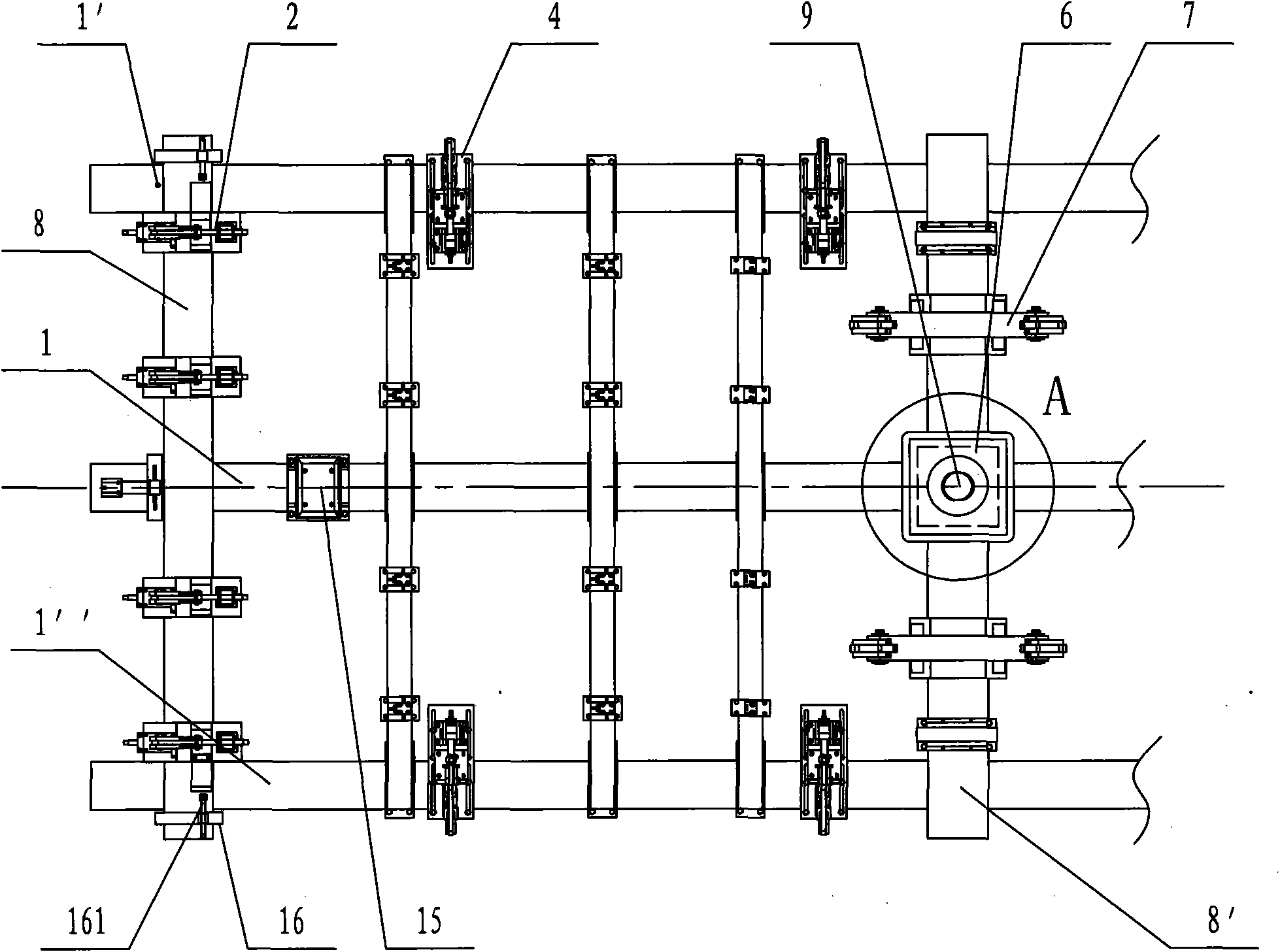
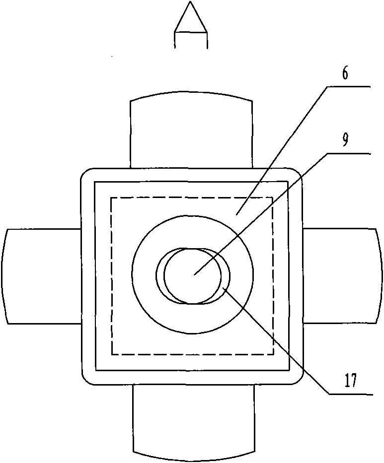
[0023] Such as figure 1 Shown is the positioning and clamping mechanism of the end-leading pillow for the underframe formal tire of the present embodiment, the main structure of the underframe formal tire is composed of three longitudinal beams 1, 1 ', 1 ", and four heel large horizontal frames 8, 8 ' (in the figure Only draw the left part of the bottom frame for the tire, and the right part is symmetrical with it), the upper end faces of the longitudinal frames 1, 1', 1" are located in the same horizontal plane (the flatness is about 1mm), and the large horizontal frames 8, 8' It is perpendicular to the vertical frames 1, 1', 1" and can be moved and positioned arbitrarily on the vertical frames 1, 1', 1". Two large horizontal frames 8 are located at the outer ends and bottoms of the vertical frames 1, 1', 1". The frame end beams correspond, and the other two large horizontal frames 8 ' are located at the longitudinal frames 1, 1 ', 1 " and correspond to the corbel beams on bo...


PUM


Abstract

The invention discloses an end traction and bolster positioning and clamping mechanism for a chassis centered tyre, which comprises an end beam positioning and clamping device fixed on an outer end large crossframe, a horizontal centering device fixed on a middle longitudinal frame between inner and outer end large crossframes, and an upper center plate positioning surface arranged on the upper end face of the middle of the inner end large crossframe, wherein the upper center plate positioning surface is provided with an upper center plate central hole positioning pin positioned in the center line of the middle longitudinal frame; and the horizontal centering device takes the center line of a chassis towing beam as a positioning reference. For the chassis centered tyre, in the chassis end traction and bolster height positioning, lower planes of two upper center plates of the end traction and bolster and the lower plane of the end beam are taken as a reference, and in the horizontal positioning, the upper center plate central hole positioning pin and the horizontal centering device are used for positioning. Therefore, the positioning and clamping mechanism is reasonable in positioning mode without manual marking, high in positioning accuracy and high in production efficiency.

Description

technical field [0001] The invention relates to a positioning and clamping mechanism for an end-tension pillow for a tire on a railway vehicle underframe, and belongs to the technical field of railway vehicle underframe tooling. Background technique [0002] At present, in the assembly process of the underframe steel structure, most of them adopt the underframe reverse assembly mode. The design and manufacture of the underframe reverse tire is simple and easy, but the assembly process has higher requirements. After the steel structure of the underframe is assembled, it is required that the levelness of the upper center plate of the underframe corbel is not greater than 0.5mm, and the height difference relative to the bearings on both sides is not greater than 3mm. Both side bearings and side bearings are in a free state. During the assembly process, the levelness of the upper center plate and the height difference between the two side bearings must be continuously measured. ...

Claims


Application Information

Patent Timeline
IPC IPC(8): B23P19/04
Inventor 何伯庆刘建军
Owner CRRC NANJING PUZHEN CO LTD
Why Eureka
Try Eureka