
Deforming grid device for ceramic brick production

A ceramic tile and grid technology, applied in the field of deformed grid devices, can solve the problems of broken pattern effect, interruption, unnatural bending, etc.

Active Publication Date: 2011-06-15
FOSHAN BOFFIN MECHANICAL & ELECTRICAL
View PDF6 Cites 0 Cited by
  • Summary
  • Abstract
  • Description
  • Claims
  • Application Information

AI Technical Summary

Problems solved by technology

[0002] As we all know, there are many varieties of polished bricks, such as speckled bricks, large-grained bricks, seepage bricks, multi-tube cloth bricks, micro-material bricks, etc. They all have their own advantages and disadvantages, but manufacturers try to make the brick surface texture as smooth as possible when producing. The effect has a natural and smooth performance. In the production process of ceramic floor tiles, most of them use oblique strip grids. Through the front and rear movement and lifting of the grids, the brick surface can produce long strip patterns, but there are also obvious shortcomings. At the fixed oblique grille, if you want to make the long strip pattern into a natural curve, you must move the grille, but in this way, the long strip pattern will be interrupted, and the bending is unnatural, breaking the ring pattern effects for production design

Method used


Image

  • Deforming grid device for ceramic brick production
  • Deforming grid device for ceramic brick production

Examples


Embodiment Construction

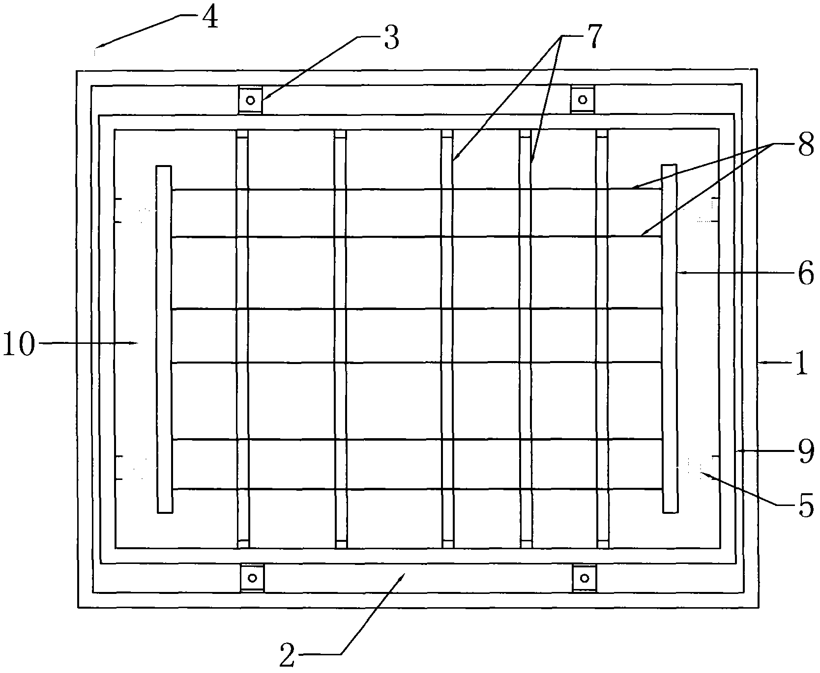
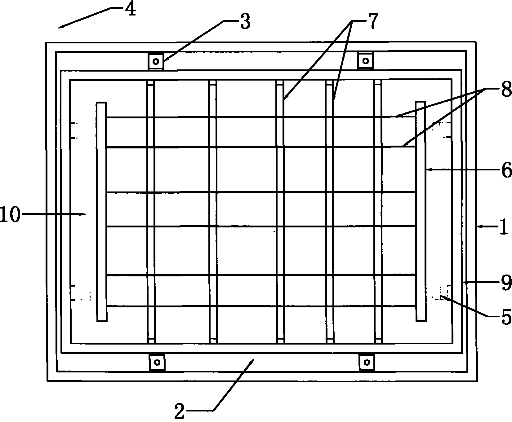
[0014] Attached below figure 1 To further illustrate the present invention, the preferred embodiment of the present invention is: the deformed grid device described in this embodiment includes an outer frame 1, and the outer frame 1 is assembled on the frame through a horizontal moving element 4. The horizontal moving element 4 of the example is a cylinder, and the outer frame 1 after assembly is provided with a deformed grille assembly 2, and the deformed grille assembly 2 includes a vertical drive element 3, a deformed sheet 8, an inner frame 9, and a deformer 10 , wherein, the inner frame 9 is assembled in the outer frame 1 through the vertical driving element 3, and the vertical driving element 3 can be a cylinder, an oil cylinder, a crank connecting rod or a rack and pinion. The vertical driving element 3 of the present embodiment is a cylinder, and the cylinder block is installed in the outer frame 1. The installed cylinder piston rod is connected with the inner frame 9....


PUM


Abstract

The invention provides a deforming grid device for ceramic brick production, comprising an outer frame, wherein the outer frame is assembled on a frame through a horizontally moving element, and a deforming grid component is arranged in the assembled outer frame. The deforming grid component comprises a vertical drive element, a deforming plate, an inner frame and a deformer, wherein the vertical drive element is assembled in the outer frame, and is connected with the inner frame; two ends of the deforming plate are connected with the internal wall of the inner frame respectively through the deformer; and a forming rod matched with the deforming plate is arranged in the inner frame. By adopting the scheme, the outer frame is driven by the horizontally moving element to move front and back onto a belt to a formed powder layer, the vertical drive element drives the inner frame to decline to the powder layer, a deformed cylinder piston rod extends out and drives a connecting beam to extrude forward, the deforming plate is bent naturally under driving of the deforming cylinder to ensure that the formed powder layer on the belt is re-formed along with the bending shape of the deforming plate, and a fired brick surface has high degree of fake nature, natural and smooth texture and no repetitiveness.

Description

Technical field: [0001] The invention relates to the technical field of ceramic production, in particular to a deformation grid device used in the production of ceramic tiles. Background technique: [0002] As we all know, there are many varieties of polished bricks, such as speckled bricks, large-grained bricks, seepage bricks, multi-tube cloth bricks, micro-material bricks, etc. They all have their own advantages and disadvantages, but manufacturers try to make the brick surface texture as smooth as possible when producing. The effect has a natural and smooth performance. In the production process of ceramic floor tiles, most of them use oblique strip grids. Through the front and rear movement and lifting of the grids, the brick surface can produce long strip patterns, but there are also obvious shortcomings. At the fixed oblique grille, if you want to make the long strip pattern into a natural curve, you must move the grille, but in this way, the long strip pattern will b...

Claims


Application Information

Patent Timeline
IPC IPC(8): B28B17/00
Inventor 梁海果严苏景
Owner FOSHAN BOFFIN MECHANICAL & ELECTRICAL
Learn More