Subassembly device of integrated automobile accelerator

A technology of accelerators and sub-assemblies, which is applied in the layout of power plant control mechanisms, vehicle components, transportation and packaging, etc., can solve the problems of complex structure, easy to wear and break wire ropes, low balance and reliability, and achieve the structure of the device. Simple, save processing time, and improve the effect of load efficiency

Active Publication Date: 2013-03-20
LIUZHOU JINYUAN MACHINERY MFG
View PDF9 Cites 0 Cited by
  • Summary
  • Abstract
  • Description
  • Claims
  • Application Information

AI Technical Summary

Problems solved by technology

[0002] The existing automobile accelerator sub-assembly is composed of pedal assembly, upper cover assembly and accelerator cable assembly. The pedal rod assembly is welded by the pedal rod and stamped cable fixing bracket. The accelerator cable assembly The steel wire rope joint is directly connected to the cable fixing bracket, without shock absorption or wire rope protection device, the balance and reliability of the car during driving are low. The edge of the stamping groove will rub against the wire rope, which is easy to wear and tear the wire rope, which reduces the life of the product; in addition, the riveting method of the steel wire rope and the wire rope joint is riveted, and the pull-off force is insufficient, and the wire rope at the riveting point is easy to break
In addition, there are too many connections between the three parts of the automobile accelerator sub-assembly currently on the market, the structure is complex, and the quality is unstable. The three parts are provided to the OEM by different suppliers. Many problems, high friction resistance of the accelerator, high failure rate of the whole vehicle, short product life, high three-guarantee claim rate and other defects
[0003] In the published patent documents, some new structures of the accelerator pedal assembly are disclosed, which to a certain extent solve the problem of too many connecting parts of the three parts of the existing automobile accelerator subassembly, but it still cannot solve the problem of the accelerator cable assembly. The steel wire rope is easy to be broken by the friction of the welded cable fixing bracket of the pedal assembly, the pull-off force of the steel wire rope and the steel wire rope joint is insufficient, and the steel wire rope at the riveting part is easy to break, etc.

Method used


Image

  • Subassembly device of integrated automobile accelerator
  • Subassembly device of integrated automobile accelerator
  • Subassembly device of integrated automobile accelerator

Examples


Embodiment 1

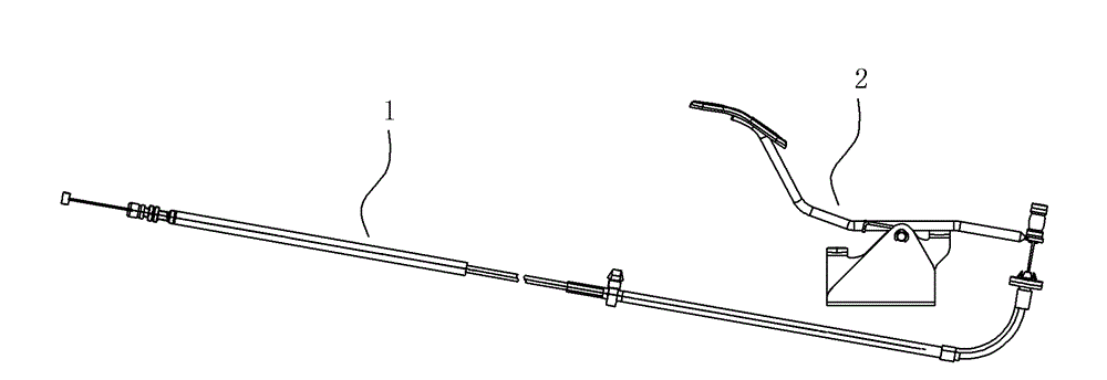
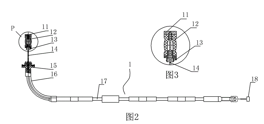
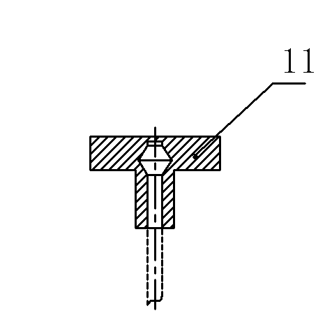
[0027] An integrated automotive accelerator subassembly (see Figure 1 to Figure 8-3 ), including accelerator cable assembly 1 and accelerator pedal assembly 2.

[0028] The accelerator pedal assembly includes a pedal rod assembly 21, a bracket welding piece 23, a return spring 22, a bushing 24 and a back ring 25, and the pedal rod assembly 21 of the accelerator pedal assembly 2 is mainly composed of a pedal rod 213 1. A pedal 214 welded at one end of the pedal rod and a rotating pin 212 fixed at the middle of the pedal rod. The other end of the pedal rod of the accelerator pedal assembly 2 is formed by stamping to cooperate with the nylon joint 13 of the accelerator cable assembly. The circular cable fixing ring 211, the pedal rod assembly 21 is installed on the bracket welding part 23 through the rotating pin shaft 212, and is positioned by the bushing 24 and the retaining ring 25, and the bracket welding part is provided with a spring limiting Position rod 234, front limit...


PUM


Abstract

The invention relates to a subassembly device of an integrated automobile accelerator, which comprises an accelerator inhaul cable assembly and an accelerator pedal assembly. The accelerator inhaul cable assembly also comprises an anti-shock pad and a nylon connector, wherein the anti-shock pad and the nylon connector are both sleeved on a steel wire; the anti-shock pad is sleeved on the lower part of a steel wire rope connector I connected with one end of the accelerator pedal assembly; and the nylon connector is sleeved on the lower part of the anti-shock pad. A round inhaul cable fixing ring matched with the nylon connector of the accelerator inhaul cable assembly is formed on one end of a pedal rod of the accelerator pedal assembly by punching; and the steel wire rope of the accelerator inhaul cable assembly is arranged on the pedal rod component of the accelerator pedal assembly through the nylon connector. The nylon connector for protecting the steel wire rope and the anti-shock pad for buffering are arranged on the accelerator inhaul cable assembly, the addition of the anti-shock pad improves the driving stability and reliability of an automobile, and the addition of the nylon connector eliminates the friction between the steel wire rope and the edge of a punched groove on an inhaul cable fixing bracket of the pedal rod.

Description

technical field [0001] The invention relates to an integrated automobile accelerator subassembly device. Background technique [0002] The existing automobile accelerator sub-assembly is composed of pedal assembly, upper cover assembly and accelerator cable assembly. The pedal rod assembly is welded by the pedal rod and stamped cable fixing bracket. The accelerator cable assembly The steel wire rope joint is directly connected to the cable fixing bracket, without shock absorption or wire rope protection device, the balance and reliability of the car during driving are low. The edge of the stamping groove will rub against the steel wire rope, which is easy to wear and tear the steel wire rope, which reduces the life of the product; in addition, the riveting method of the steel wire rope and the steel wire rope joint is riveted, and the pull-off force is insufficient, and the steel wire rope at the riveting point is easy to break. In addition, there are too many connections b...

Claims


Application Information

Patent Timeline
Patent Type & Authority Patents(China)
IPC IPC(8): B60K26/04B60K26/02
Inventor 邓加尊黄晓练覃朝兵金建根马春文
Owner LIUZHOU JINYUAN MACHINERY MFG
Why Eureka
Try Eureka