Heat pipe battery

A heat pipe, battery technology, used in engine components, machines/engines, mechanical equipment, etc.

Inactive Publication Date: 2011-06-15
NANJING UNIV OF AERONAUTICS & ASTRONAUTICS
View PDF5 Cites 1 Cited by
  • Summary
  • Abstract
  • Description
  • Claims
  • Application Information

AI Technical Summary

Problems solved by technology

So far, no one has combined heat pipes with disk turbines and generators, and made comprehensive use of them to generate electricity

Method used


Image

  • Heat pipe battery
  • Heat pipe battery
  • Heat pipe battery

Examples


Embodiment Construction

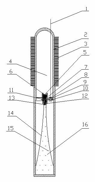
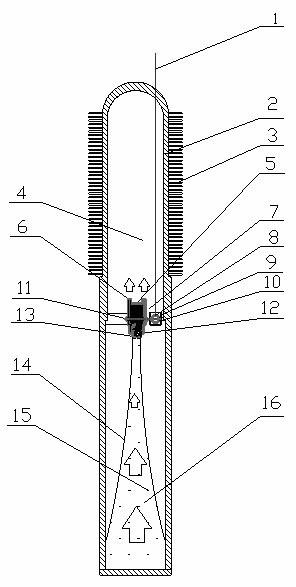
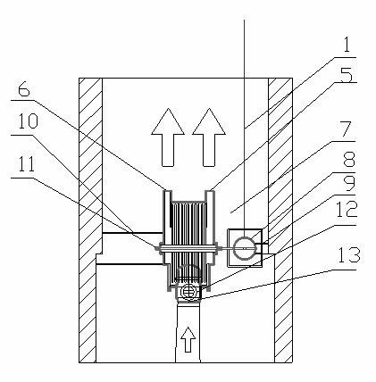
[0016] Referring to the accompanying drawings, the present invention provides a heat pipe battery, which includes a heat pipe, a disk turbine 5 and a generator 8 . The heat pipe is divided into three chambers: the evaporating chamber 16, the adiabatic chamber 7, and the condensing chamber 4. The disk turbine and generator are installed in the adiabatic chamber. In the illustrated example, the heat pipe is a gravity heat pipe. The working medium 15 in the evaporation chamber 16 completes the circulation by its own gravity. The siphon channel 14 is a tapered nozzle. The working medium 15 is heated and evaporated into gas in the evaporation chamber 16, and the gas passes through the siphon The passage 14 accelerates the flow upwards, and when reaching the throat of the siphon pipe 14, the vapor velocity reaches a maximum. The throat part of the siphon channel 14 is connected with the steam inlet pipe 13 by flange bolts, and the figure 2 It can be seen that the gas enters the di...


PUM


Abstract

The invention relates to a heat pipe battery which belongs to the technical field of heat energy utilization. The heat pipe battery provided by the invention comprises a gravity heat pipe, a disk turbomachine and a motor, wherein the disk turbomachine (5) and the motor (8) are horizontally installed in the heat insulating section cavity (7) of the heat pipe through a bracket (10); a disk turbomachine rotor (11) is connected with a generator (8); a siphon (14) is installed in the evaporating section cavity (4) of the gravity heat pipe; and the outlet of the siphon (14) is hermetically connected with the steam inlet channel (13) of the disk turbomachine (5). The heat pipe battery provided by the invention has the advantages of energy conservation, high efficiency and environmental friendliness.

Description

technical field [0001] The invention relates to a heat pipe battery and belongs to the technical field of heat energy utilization. Background technique [0002] With the increasing attention and promotion of energy-saving technology, the utilization of heat energy has been mainly studied as a main energy-saving direction. There have been some studies on the utilization of thermal energy. As an energy-saving and efficient device, heat pipes have been used in various fields. The development and utilization of heat pipes has reached a very mature stage. However, research on heat pipes in the prior art mainly focuses on regulating temperature distribution, recovering waste heat, and the like. So far, no one has combined heat pipes with disk turbines and generators, and made comprehensive use of them to generate electricity. Invention content: [0003] The object of the present invention is to provide an energy-saving, high-efficiency and environment-friendly heat pipe ba...

Claims


Application Information

Patent Timeline
Patent Type & Authority Applications(China)
IPC IPC(8): F01D15/10F01D17/10
Inventor 韩东叶莉顾昂姚君磊梁林焦炜琦郭新贤申耀阳陈慧赵锦杰
Owner NANJING UNIV OF AERONAUTICS & ASTRONAUTICS
Why Eureka
Try Eureka