Bolted connection structure and lock washer and luggage rack thereof
A technology of stop washer and connection structure, which is applied in the field of automobile luggage rack, can solve the problems of limited installation and operation space, achieve good stop effect, and fast and convenient installation process
Active Publication Date: 2011-06-15
NINGBO XINTAI MACHINERY
View PDF9 Cites 15 Cited by
- Summary
- Abstract
- Description
- Claims
- Application Information
AI Technical Summary
Problems solved by technology
Common structures include some stop gaskets, self-locking structures, etc., but when the installation and operation space is limited, how to stop becomes a problem
Method used
View moreImage
Smart ImageViewing Examples
Examples
Embodiment Construction
Login to View More PUM
 Abstract
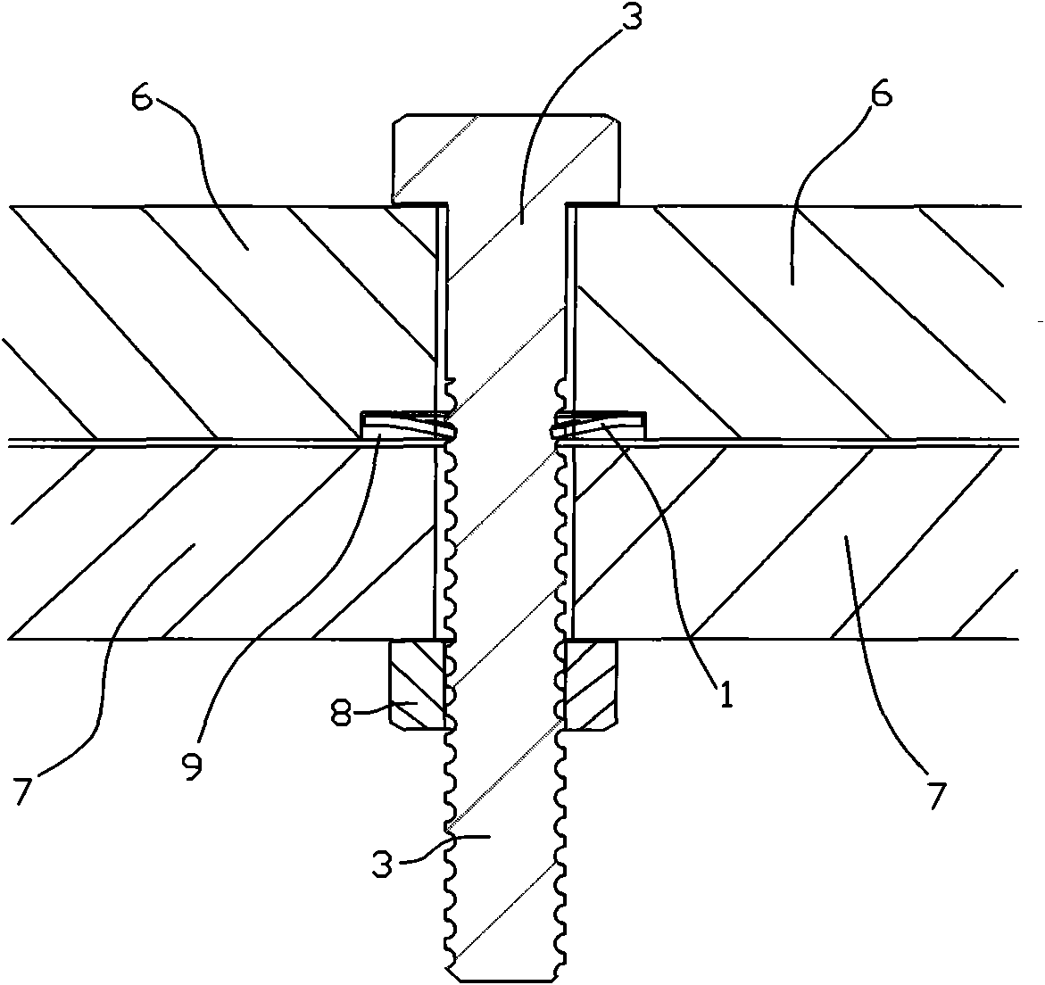
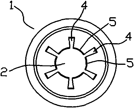
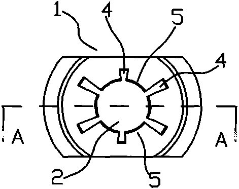
The invention provides a bolted connection structure capable of effectively reducing bolt movement and a lock washer thereof, and an automobile luggage rack with the structure. The center of the lock washer (1) is provided with a round hole (2), and the diameter of the round hole (2) is slightly larger than the external diameter of threads of a bolt (3) to be locked by the round hole (2), so thatthe round hole (2) and the bolt (3) are in interference fit after the bolt (3) is screwed in; and the periphery of the round hole (2) is provided with a plurality of grooves (4) among which a plurality of deformation teeth (5) are formed. In the bolted connection structure suitable for the automobile luggage rack, the bolt (3) passes through two connected pieces (6 and 7), the lock washer (1) is screwed in or pressed in the bolt (3), and the deformation teeth (5) are deformed to be embedded into the threads of the bolt (3); or the bolt (3) passes through an upper connected piece (6), the lockwasher (1) is screwed in or pressed in the bolt (3), the bolt (3) passes through a lower connected piece (7), and a nut (8) is screwed in.
Description
Bolted connection structure and its stop washer and luggage rack technical field The invention relates to a bolt connection structure and its stop washer, and an automobile luggage rack adopting the structure. Background technique Generally, when two parts are to be connected with freely movable bolts and nuts, if there is no structure to limit the bolts, the bolts will move upwards when the nuts are installed, causing inconvenience in installation. Especially for products such as luggage rack installation, where one bolt and nut are outside the car and the other is inside the car, it is inconvenient to hold down the bolt, the demand for a small structure that can limit the bolt's upward movement is particularly strong. Common structures include some stop gaskets, self-locking structures, etc., but when the installation and operation space is limited, how to stop becomes a problem. The present invention is just to solve this problem. Contents of the invention The te...
Claims
Login to View More Application Information
Patent Timeline
 IPC IPC(8): B60R9/04F16B39/24
Inventor 王海宏
Owner NINGBO XINTAI MACHINERY
Features
- R&D
- Intellectual Property
- Life Sciences
- Materials
- Tech Scout
- Unparalleled Data Quality
- Higher Quality Content
- 60% Fewer Hallucinations
Learn More Browse by: Latest US Patents, China's latest patents, Technical Efficacy Thesaurus, Application Domain, Technology Topic, Popular Technical Reports.
© 2025 PatSnap. All rights reserved.Legal|Privacy policy|Modern Slavery Act Transparency Statement|Sitemap|About US| Contact US: help@patsnap.com


