Range gating based laser imaging synchronous control system

A synchronous control and laser imaging technology, which is applied in the direction of electrical program control, sequence/logic controller program control, etc., can solve the problems of gating imaging effect, stability is difficult to guarantee, real-time setting and other problems, so as to achieve convenient handling and installation, good real-time performance, light weight effect

Active Publication Date: 2011-06-15
北京中科盛视科技有限责任公司
View PDF4 Cites 14 Cited by
  • Summary
  • Abstract
  • Description
  • Claims
  • Application Information

AI Technical Summary

Problems solved by technology

At present, most of the synchronous control systems based on range-gated laser imaging technology can only perform some simple settings for these parameters, which is poor in flexibility, difficult to guarantee stability, and cannot be set in real time, so it is more troublesome to use and has a greater impact on the effect of gated imaging. big impact

Method used


Image

  • Range gating based laser imaging synchronous control system
  • Range gating based laser imaging synchronous control system
  • Range gating based laser imaging synchronous control system

Examples


Embodiment Construction

[0029] In order to make the object, technical solution and advantages of the present invention clearer, the present invention will be described in further detail below in conjunction with specific embodiments and with reference to the accompanying drawings.

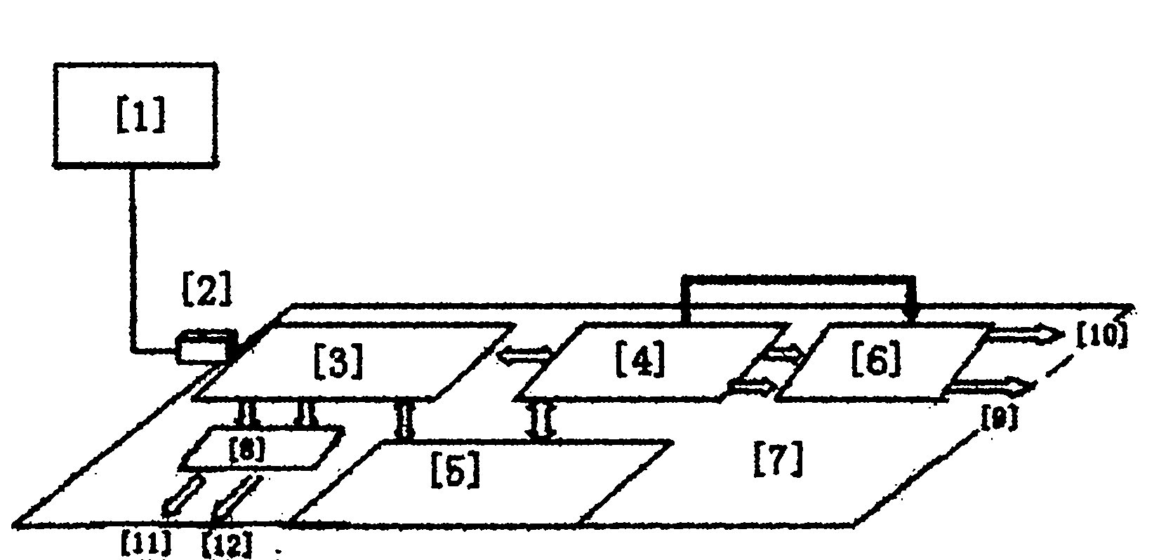
[0030] Such as figure 1 as shown, figure 1 It is a schematic structural diagram of a laser imaging synchronous control system based on distance gating provided by the present invention. The system includes a computer software interface 1, a USB interface 2, a microcontroller 3, an FPGA 4, a peripheral circuit 5, a delay fine-tuning circuit 6, and a PCB board 7 and operational amplifier 8, wherein the data sent from the computer software interface 1 is transmitted to the microcontroller 3 through the USB interface 2; The control parameters of the delay and mutual delay of the trigger signal are transmitted to FPGA4; after receiving these control parameters, FPGA4 generates the trigger pulse laser and ICCD with adjustable ...


PUM


Abstract

The invention discloses a range gating based laser imaging synchronous control system. The system comprises a computer software interface, a USB interface, a micro controller, an FPGA (field programmable gate array), a peripheral circuit, a time delay fine tuning circuit, a PCB (printed circuit board) and an operational amplifier, wherein the data sent out from the computer software interface aretransmitted to the micro controller by virtue of the USB interface; the micro controller transmits the frequencies, pulse width parameters of triggering signals of a pulse laser and an ICCD (intensified charge coupled device) and control parameters of delays and mutual delay of the two triggering signals to the FPGA; the FPGA generates two TTL (transistor-transistor logic) signals which are used for triggering the pulse laser and the ICCD and are adjustable (coarse tuning) in frequency, pulse width, delay and interactive delay after receiving the control parameters, the two signals are used for realizing fine tuning on the delays and the interactive delay by virtue of the time delay fine tuning circuit, and finally the pulse laser and the ICCD are triggered. By applying the system in the invention, the aim of flexibly setting imaging parameters can be achieved; and meanwhile, the structure is compact, and the system is convenient to carry and use and has good stability.

Description

technical field [0001] The present invention relates to the technical field of laser imaging based on range gating, in particular to a synchronous control system for laser imaging based on range gating, which is suitable for controlling the frequency and pulse width of each trigger signal of a pulse laser and an ICCD when laser imaging is based on range gating parameters, as well as the control parameters of the delay and mutual delay of the two trigger signals, the control parameters of the output power of the pulse laser, the gain control parameters of the ICCD, etc. Real-time automatic delay and mutual delay (convenient for delay compensation) and ICCD trigger signal in control occasions with adjustable delay steps. Background technique [0002] At present, the range-gated laser imaging technology is widely used in surveillance, reconnaissance and security fields. It is mainly through the timing control between the pulsed laser and the imaging detector, according to the t...

Claims


Application Information

Patent Timeline
Patent Type & Authority Applications(China)
IPC IPC(8): G05B19/05
Inventor 杨金宝范松涛周燕
Owner 北京中科盛视科技有限责任公司
Why Eureka
Try Eureka