Shaft brake disc, in particular for a rail vehicle

A rail vehicle and brake disc technology, applied in the direction of brake discs, brake types, brake components, etc., can solve problems such as unfavorable cost structures, and achieve the effect of avoiding bending stress and optimizing force introduction

Inactive Publication Date: 2011-06-15
KNORR BREMSE SYST FUR SCHIENENFAHRZEUGE GMBH
View PDF7 Cites 9 Cited by
  • Summary
  • Abstract
  • Description
  • Claims
  • Application Information

AI Technical Summary

Problems solved by technology

[0007] In addition to these functional disadvantages, an unfavorable cost structure results when manufacturing the axle brake disc, in particular due to the locking element being manufactured as a special part

Method used


Image

  • Shaft brake disc, in particular for a rail vehicle
  • Shaft brake disc, in particular for a rail vehicle
  • Shaft brake disc, in particular for a rail vehicle

Examples


Embodiment Construction

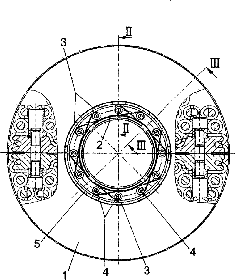
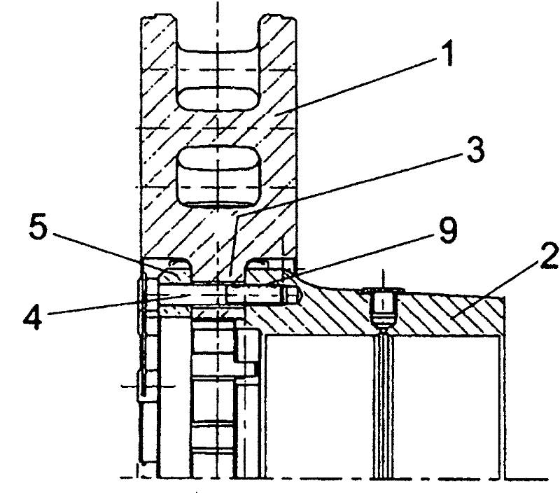
[0026] exist figure 1 A shaft brake disc is shown in , which has a friction ring 1 which is connected to a hub 2 via screws 4 .

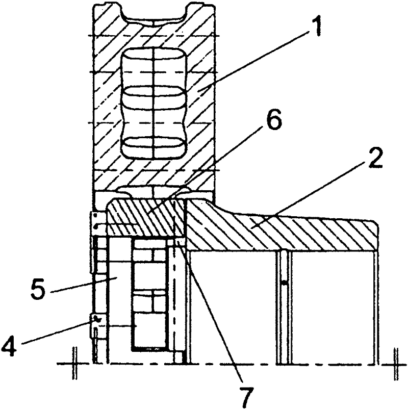
[0027] Here, the screws 4 are screwed into threaded holes 9 provided on the end side in the hub 2 , and they are guided with their rods through the through-holes 10 of the friction ring 9 and the through-holes 8 of the tensioning ring 5 ( Figure 4 ), the tensioning ring rests on the connecting flange 3 of the friction ring 1 and more precisely on the side opposite the hub 2 .

[0028] The tensioning ring 5 forms a seat for the screw 4 , ie its head, via which the friction ring 1 is pressed against the hub 2 .

[0029] The connecting flanges 3 of the friction ring 1 are distributed evenly over the inner circumference of the friction ring and extend radially inwards.

[0030] According to the invention, the tensioning ring 5 and the hub 2 engage with each other in a form-fitting manner. For this purpose, the one-piece tensioning ring 5 has four, p...


PUM


Abstract

A shaft brake disc, in particular for a rail vehicle, comprising a friction ring (1) fastened to a hub (2) by way of screws (4) that are passed through a clamp ring (5) at the inner periphery of the friction ring (1) that sits against support flanges, said clamp ring forming a backing support for the screws (4), is adapted so that the clamp ring (5) and the hub (2) engage one another in a form-fitted manner.

Description

technical field [0001] The invention relates to an axle brake disk according to the preamble of claim 1 , in particular an axle brake disk for a rail vehicle. Background technique [0002] Such an axle brake disc is known from DE 38 14 614 A1. For fastening the friction ring on the hub or axle of the rail vehicle, there is provided a connecting flange arranged on the inner circumference of the friction ring and extending radially inwards, through which a screw engaging into the hub is guided . [0003] In this case, the tensioning ring through which the screw is guided and rests with its head or the like is also intended to prevent the screw connection from being subjected to bending loads when the position of the interconnected parts changes. . [0004] The relative rotation prevention is achieved via special locking elements which are held in the hub on the one hand and engage in the friction ring on the other hand. These locking elements are used to transmit the braki...

Claims


Application Information

Patent Timeline
Patent Type & Authority Applications(China)
IPC IPC(8): F16D65/12
CPCF16D2065/1316F16D2065/1312F16D65/124F16D2065/1392F16D2065/136F16D2065/1384F16D65/123F16D2065/1328F16D65/00F16D65/12
Inventor P·塞弗特M·尼斯纳R·卢茨
Owner KNORR BREMSE SYST FUR SCHIENENFAHRZEUGE GMBH
Why Eureka
Try Eureka