Cradle stand for electrolysis cell

A cradle frame and electrolytic cell technology, which is applied in the field of aluminum electrolytic cells, can solve the problems of arching and deformation at the bottom of the tank shell, and achieve the effects of reduced height, small deformation and reasonable stress.

Active Publication Date: 2011-06-29
GUIYANG AL-MG DESIGN & RES INST
View PDF3 Cites 5 Cited by
  • Summary
  • Abstract
  • Description
  • Claims
  • Application Information

AI Technical Summary

Problems solved by technology

[0006] The technical problem to be solved by the present invention is to provide a cradle frame for an electrolytic cell, which has a simple structure and reliable operation, can improve the mechanical performance of the cradle frame and the interior of the electrolytic cell, and at the same time greatly reduce the cost of the electrolytic cell to overcome the The arching deformation at the bottom of the tank shell caused by the expansion of the tank shell in the prior art causes a large shear force and bending moment at the end of the cradle frame, and shearing and tearing damage occur at the root of the cradle frame.

Method used


Image

  • Cradle stand for electrolysis cell
  • Cradle stand for electrolysis cell
  • Cradle stand for electrolysis cell

Examples


Embodiment 1

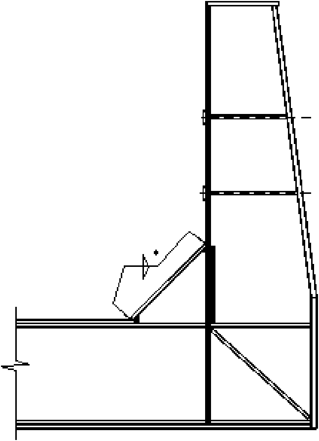
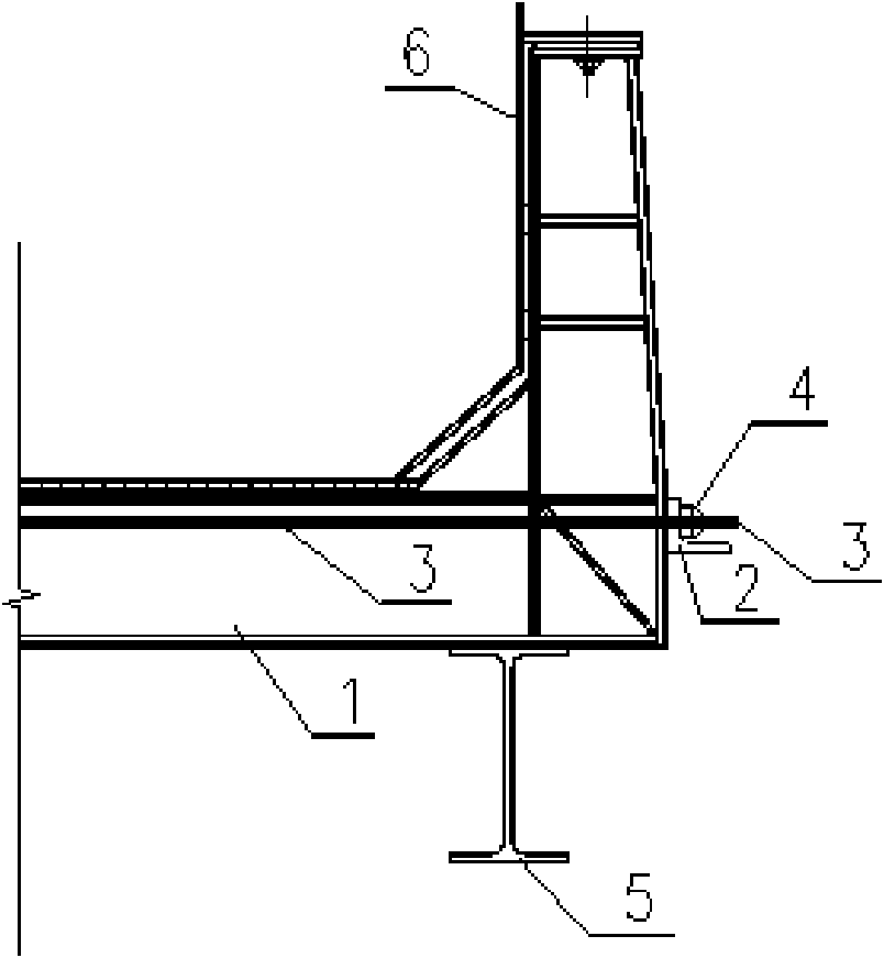
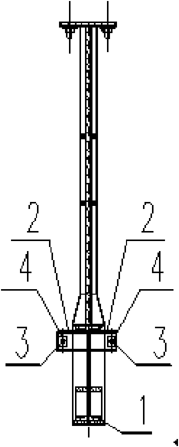
[0017] Embodiment 1 of the present invention: the electrolyzer cradle frame of the present invention is as figure 1 As shown (the cradle frame of the electrolytic cell is symmetrical on the left and right, and only half of it is shown in the figure), it supports the cell shell 6 of the electrolytic cell, which includes a bottom girder 1 located at the bottom of the cradle frame, and an electrolytic cell AB beam 5 is arranged below the bottom girder 1, Prestressed tie rods 3 are interspersed and fixed on the bottom girder 1 . There are two prestressed tie rods 3, which are respectively located on both sides of the bottom girder 1. The prestressed tie rods 3 are made of high-strength steel bars or steel strands, and both ends are provided with threads, which can be equipped with high-strength bolts. The left and right ends of the prestressed tie rods 3 are also provided with anchor ends 4 at the end of the prestressed tie rods, which are anchored together with the fulcrums 2 of ...


PUM


Abstract

The invention discloses a cradle stand for an electrolysis cell. The cradle stand comprises a bottom girder (1) at the bottom of the cradle rack, wherein a pre-stress pull rod (3) passes through and is fixed on the bottom girder (1). By applying pre-stress to the bottom girder of the cradle stand of the electrolysis cell in advance, a component combining upper pure bending force with lower pure bending force of the bottom girder of the cradle stand is stressed instead of a lower pure bending part, so that the bottom girder of the cradle stand is prevented the over deforming because of bendingof the lower side of the bottom girder, stress of a high-strength material is sufficiently played, the structure receives the pre-pressure applied by the pre-stress pull rod before the structure is subject to a loading action, the loading formed pulling stress of the bottom girder of the cradle stand caused by bending of the lower side is reduced or counteracted, the thickness of bottom girder type steel webs, height of the bottom girder and usage of flange materials at two ends are effectively reduced, and the aims of reasonable stress and less deformation are achieved.

Description

technical field [0001] The invention relates to a cradle frame structure for an electrolytic cell, belonging to the technical field of aluminum electrolytic cells. Background technique [0002] The cradle frame is the key component of electrolytic aluminum production. Modern large-scale aluminum electrolytic cells mostly use cradle-type shells, and the lower structure is mainly composed of electrolytic cell shells and a series of cradle frames. The long side load of the tank shell is mainly borne by the cradle frame. In the actual use process, it is found that the bowing deformation of the bottom of the tank shell directly affects the working capacity of the tank shell. The main reason for the arching deformation at the bottom of the electrolytic cell shell is that as the electrolytic cell starts to operate, the temperature at the bottom of the cell rises, and under the action of expansion stress absorbed by the inner liner, welding internal stress and thermal stress, the c...

Claims


Application Information

Patent Timeline
Patent Type & Authority Applications(China)
IPC IPC(8): C25C3/10
Inventor 施亮郑莆余详兴
Owner GUIYANG AL-MG DESIGN & RES INST
Why Eureka
Try Eureka