Eureka AIR delivers breakthrough ideas for toughest innovation challenges, trusted by R&D personnel around the world.

Method for designing reinforced concrete foundation or pile cap

A reinforced concrete and design method technology, applied in the field of reinforced concrete foundation or pile cap design, can solve the problems of large calculation cracks and multiple ordinary steel bars, and achieve the effects of improving fatigue resistance, saving materials, and being easy to popularize and apply

Active Publication Date: 2011-03-30
POWERCHINA XIBEI ENG
View PDF0 Cites 0 Cited by
  • Summary
  • Abstract
  • Description
  • Claims
  • Application Information

AI Technical Summary

Problems solved by technology

[0002] In recent years, the foundations of new wind power towers in my country are generally in the form of natural foundations and pile foundations, but there are also the following main problems: 1. The foundation or pile caps bear large vertical tension, and the foundation or pile caps are resistant This force generally adopts more ordinary steel bars; 2. Since the foundation or pile cap bears a large vertical tensile force, the calculated crack is relatively large under the action of tension.

Method used


Image

  • Method for designing reinforced concrete foundation or pile cap
  • Method for designing reinforced concrete foundation or pile cap
  • Method for designing reinforced concrete foundation or pile cap

Examples


Embodiment 1

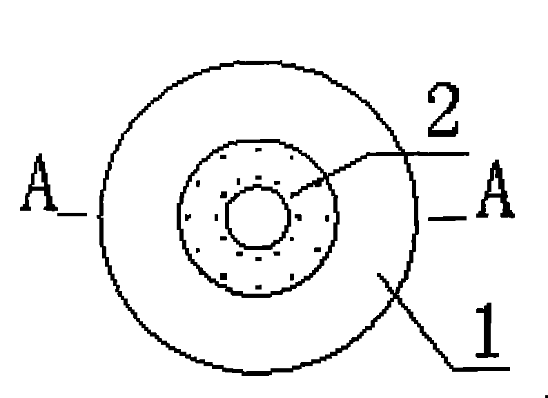
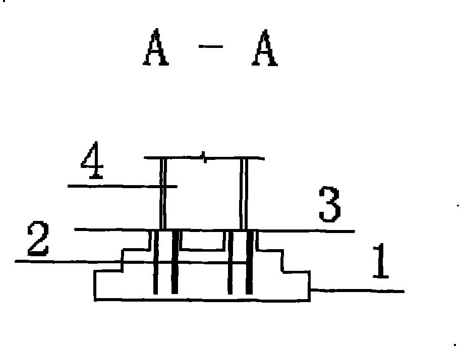
[0025] Embodiment 1 structure such as figure 1 , figure 2 Shown is a schematic diagram of the prestressed structure adopted by the reinforced concrete foundation 1 in the vertical direction, which includes a superstructure 4 and a reinforced concrete foundation 1, and a prestressed steel bar 2 is embedded in the reinforced concrete foundation 1 connected under the superstructure 4. The outer diameter of the reinforced concrete foundation 1 decreases successively from bottom to top and is in the shape of a superimposed circular platform. The upper end of the circular platform is a hollow structure, and the prestressed steel bars 2 are uniformly and vertically distributed on the inner cylinder of the hollow structure. The quantity of embedded vertical prestressed steel bars 2 is 1 / 3-1 / 5 of ordinary steel bars. The number of common steel bars is a well-known technology in the art. The strength of prestressed steel bars is 3 to 5 times that of ordinary steel bars, so the amount...

Embodiment 2

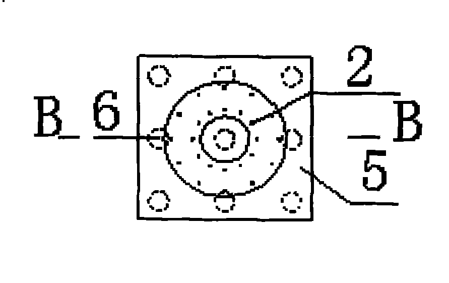
[0026] Embodiment 2 structure such as image 3 , Figure 4 As shown, it is a schematic diagram of the prestressed structure used in the vertical direction of the reinforced concrete pile cap 5. Others include the upper structure 4 and the reinforced concrete pile cap 5, and the reinforced concrete pile cap 5 connected under the upper structure 4 is embedded with a prestressed structure. Stress reinforcement 2. The reinforced concrete pile cap 5 is a hollow cylindrical structure, the hollow cylindrical bottom is a closed plane, and several piles 6 are connected under the closed plane; the prestressed steel bars 2 are uniformly and vertically distributed on the hollow inner cylinder. The quantities, high-strength materials and cross-sectional dimensions used in Embodiment 2 are the same as those in Embodiment 1.

[0027] When in use, construct the foundation as shown in the figure, the reinforced concrete foundation 1 or the reinforced concrete pile cap 5 is different from the...


PUM


Abstract

The invention relates to the field of towering buildings, in particular to a method for designing a reinforced concrete foundation or a pile cap. The device adopted in the method comprises an upper structure and a natural foundation or a pile foundation, and is characterized in that the reinforced concrete foundation (1) or the reinforced concrete pile cap (5) that is connected under the upper structure (4) is internally embedded with pre-stressed reinforcement (2). The method ensures that the reinforced concrete foundation or the pile cap adopts the pre-stressed structure in vertical direction, the force of the foundation or the pile cap is more reasonable, and the foundation or the pile cap has better crack resistance and stability.

Description

technical field [0001] The invention relates to the field of high-rise building construction, in particular to a design method for a reinforced concrete foundation or a pile cap. Background technique [0002] In recent years, the foundations of new wind power towers in my country are generally in the form of natural foundations and pile foundations, but there are also the following main problems: 1. The foundation or pile caps bear large vertical tension, and the foundation or pile caps are resistant This force generally adopts more ordinary steel bars; 2. Since the foundation or pile cap bears a large vertical tensile force, the calculated crack is relatively large under the action of tension. How to solve the above contradictions to overcome the above-mentioned problems without affecting the construction speed is the problem to be solved by the present invention. Contents of the invention [0003] The purpose of this invention is to provide a new type of foundation or pi...

Claims


Application Information

Patent Timeline
Patent Type & Authority Patents(China)
IPC IPC(8): E02D27/42E02D27/14
Inventor 石波
Owner POWERCHINA XIBEI ENG
Why Eureka
Eureka Blog
Learn More