

Tensile cross grouting anchor rod device
A technology of grouting bolts and bolts, which is applied to the installation of bolts, mining equipment, earthwork drilling and mining, etc. It can solve the problems of not considering the coordination of surrounding rock and structural degeneration and stress concentration, and only considering the coordination of tunnel structure deformation. , to achieve the effect of convenient construction process, low cost and simple principle
Inactive Publication Date: 2011-06-29
TONGJI UNIV
View PDF7 Cites 1 Cited by
- Summary
- Abstract
- Description
- Claims
- Application Information
AI Technical Summary
Problems solved by technology
This method only considers the deformation coordination of the tunnel structure, but does not consider the deformation coordination and stress concentration of the surrounding rock and structure, and needs to be combined with other pre-reinforcement measures
Method used
View moreImage
Smart ImageViewing Examples

Examples
Embodiment Construction
Login to View More PUM
 Abstract
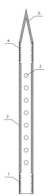
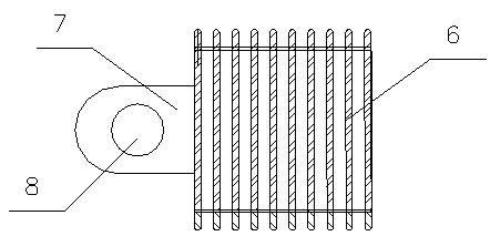
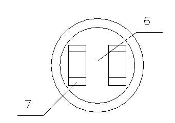
The invention relates to a tensile cross grouting anchor rod device, in particular to a device which has combined functions of a grouting pipe and an anchor rod and is capable of connecting a tunnel support and a surrounding rock or connecting closely spaced tunnel supports and a surrounding rock into a whole. The device comprises an anchor rod, a connector and a steel strand. The steel strand is wound and tied on an initial tunnel support and is fixed on the anchor rod by the connector, and the anchor rod and the connector are in threaded connection. After grouting, the hollow anchor rod is integrated with the surrounding rock, and the tunnel support and the surrounding rock in a grouting range are connected firmly. For closely spaced tunnels, the anchor rod runs through middle rock and the two ends of the anchor rod are connected to the initial tunnel support to generate a cross effect; while for common tunnels, one end of the anchor rod is connected with the initial tunnel support and the other end of the anchor rod is inserted into the tunnel surrounding rock to increase the tensile effect of the anchor rod. The device can improve the integrity of the tunnel structure and the surrounding rock and reduce the deformation of the surrounding rock and the structure.
Description
A tension-resistant, opposite-tension grouting anchor device technical field The invention relates to an auxiliary method for tunnel construction, and specifically refers to a tunnel reinforcement measure, that is, a pair-tensioning and anti-tensioning grouting bolt device. Background technique In the process of tunnel engineering construction, under some geological conditions, the self-stabilization ability of the surrounding rock of the tunnel is poor, or even has no self-stabilization ability, and it is difficult to excavate and form holes; There are problems such as bias influence and uncoordinated deformation after the tunnel is completed. In order to improve the strength of the surrounding rock and overcome the effects of bias pressure and uneven deformation, it is necessary to reinforce the surrounding rock. Currently commonly used reinforcement measures include setting anchor rods and grouting reinforcement. By setting bolts into the loose surrounding rocks, the ...
Claims
Login to View More Application Information
Patent Timeline
 IPC IPC(8): E21D21/00
Inventor石景山王长丹周顺华
OwnerTONGJI UNIV