Supercharge Your Innovation With Domain-Expert AI Agents!

Ball screw with backflow component

A ball screw and component technology, applied in belts/chains/gears, mechanical equipment, transmissions, etc., can solve the problems of increased manufacturing costs, poor processing, and high noise

Active Publication Date: 2011-06-29
HIWIN TECH
View PDF1 Cites 0 Cited by
  • Summary
  • Abstract
  • Description
  • Claims
  • Application Information

AI Technical Summary

Problems solved by technology

[0002] see figure 1 As shown in the figure, it is a configuration method of the return component and the nut of the ball screw in the known technology. The return component 2 is installed on the nut 1 with low lead (small lead angle) or more than two rolling grooves 11 , due to the limitations of the above two conditions, the thickness D between the rolling grooves 11 of the nut 1 is relatively thin, and in order to install the return assembly 2, an installation groove must be provided on the nut 1, and the contour of the installation groove must match the The shape of the return component 2, and the shape of the return component 2 is generally rectangular as shown in the figure, so it is impossible to set the installation groove with the same outline as the return component 2 on the nut 1, if it is set, it will be as shown in the figure The same causes damage to the rolling groove 11 X, and relatively, the rolling elements cannot run in the rolling groove 11, so the return assembly 2 cannot be installed in a low lead (smaller lead angle) or more than two rolling grooves 11 Nut 1
[0003] However, in order to improve the above-mentioned known problems, the return assembly is installed on a nut with a low lead (smaller lead angle) or more than two rolling grooves. Japanese Patent Publication No. JP2005-233238 has a through nut The return holes at the two ends of the axial direction are provided with two return components at both ends of the return hole. Smaller lead or multiple spiral raceways lead to thinner flesh between the spiral raceways. In order to smoothly install the return component on the nut, a part of the return channel of the return component is designed on the nut, and The return channel on the nut has a curved structure and the surface is a curved surface, so it is not easy to process, and the processing time is relatively long, and the relative manufacturing cost will also increase
And even if the processing is completed, it may not match the return channel on the return component, and because the return channel is a curved structure, the rolling parts running here will definitely collide with the surface of the return channel, and part of the return channel is made of metal , so the noise generated by its impact is also relatively high, so the patented technology still cannot completely overcome the problems caused by installing the return component on a nut with a low lead (small lead angle) or more than two rolling grooves

Method used


Image

  • Ball screw with backflow component
  • Ball screw with backflow component
  • Ball screw with backflow component

Examples


Embodiment Construction

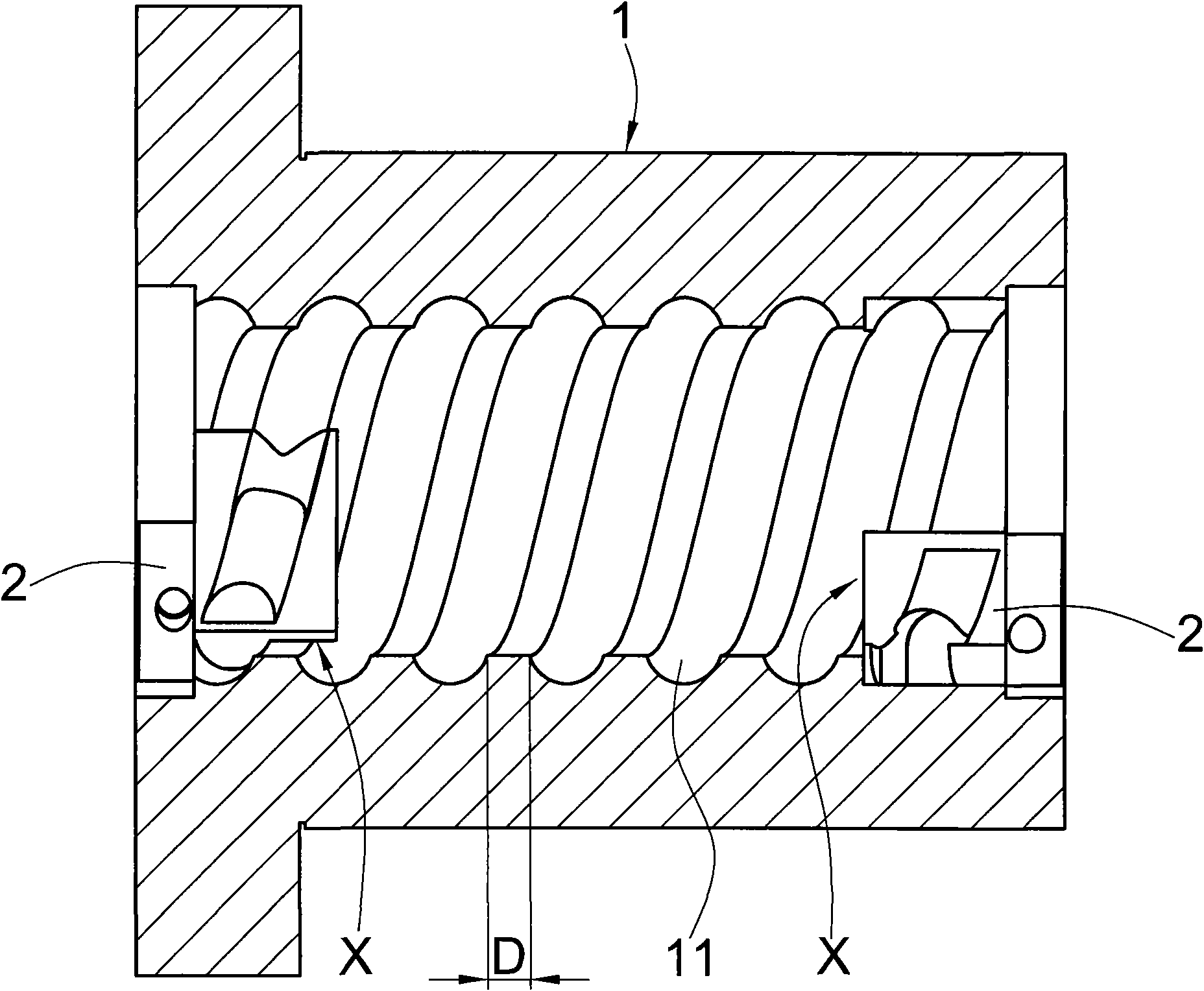
[0027] see Figure 2 to Figure 7 As shown, the present invention is a ball screw with a return assembly, which includes:

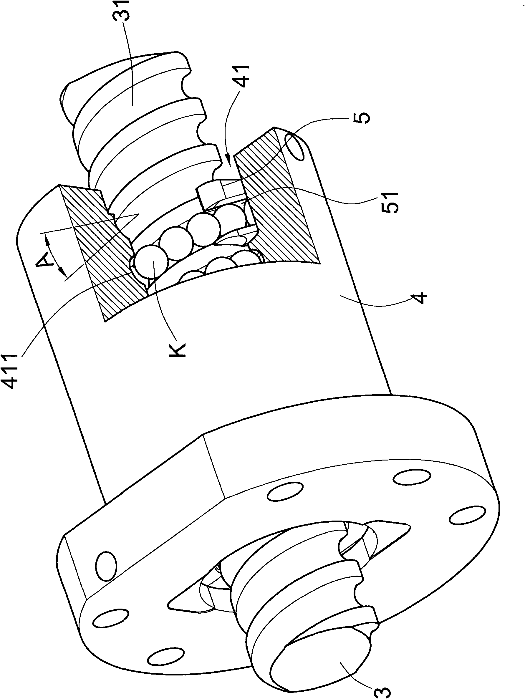
[0028] A screw 3, the outer edge of which is provided with a spiral rolling groove 31;

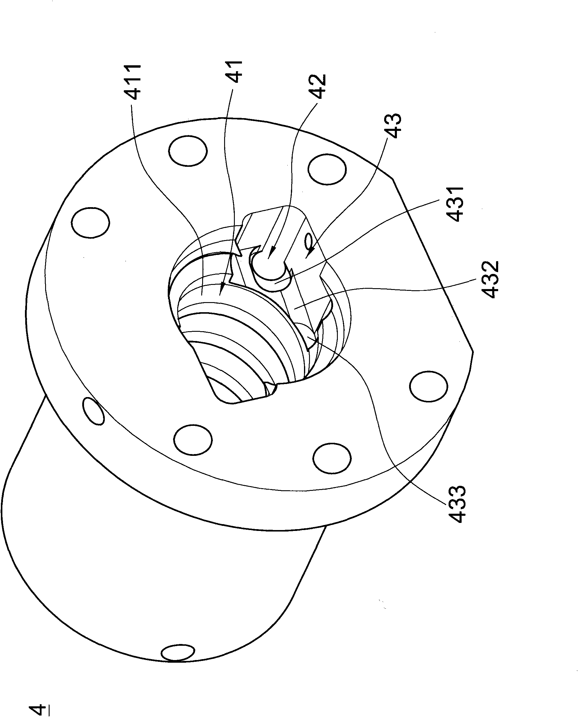
[0029] A nut 4, which is provided with a through hole 41 for the screw rod 3 to pass through, the inner edge of the through hole 41 is provided with a rolling groove 411 opposite to the rolling groove 31, and the rolling groove 411 and the rolling groove 31 form a load path , the load path has a lead angle A, and the nut 4 is provided with a return hole 42 that runs through both ends of the nut 4 in an axial direction, and a return hole 42 that is arranged at both ends of the return hole 42 and connects with the rolling groove 411 Mounting groove 43;

[0030] Two return components 5, which are arranged in the installation groove 43, the return component 5 is provided with a return channel 51, and the two ends of the return channel 51 are respectively connected to the...


PUM


Abstract

By modifying the generally known profile of a mounting groove formed on a nut, the invention solves the problem that teeth breaking is caused when the mounting groove is formed on the nut with a low lead (namely, a lower lead angle) or more than two rolling ditches. To process and form the mounting groove, all that is needed is to use a facing mill, so as to reduce the manufacturing cost. All backflow channels in the invention are arranged in a backflow component, so as to improve the fitting accuracy between a backflow hole formed on the nut and a load path. Therefore, the operation of a rolling element can be smoother, and the noise can be reduced.

Description

technical field [0001] The invention relates to a return assembly of a linear transmission assembly, in particular to the arrangement of the return assembly and a nut of a ball screw. Background technique [0002] see figure 1 As shown in the figure, it is a configuration method of the return component and the nut of the ball screw in the known technology. The return component 2 is installed on the nut 1 with low lead (small lead angle) or more than two rolling grooves 11 , due to the limitations of the above two conditions, the thickness D between the rolling grooves 11 of the nut 1 is relatively thin, and in order to install the return assembly 2, an installation groove must be provided on the nut 1, and the contour of the installation groove must match the The shape of the return component 2, and the shape of the return component 2 is generally rectangular as shown in the figure, so it is impossible to set the installation groove with the same outline as the return compo...

Claims


Application Information

Patent Timeline
Patent Type & Authority Applications(China)
IPC IPC(8): F16H25/22
Inventor 李玉山
Owner HIWIN TECH
Features
  • R&D
  • Intellectual Property
  • Life Sciences
  • Materials
  • Tech Scout
  • Unparalleled Data Quality
  • Higher Quality Content
  • 60% Fewer Hallucinations
Learn More