Lighter

A lighter and steamer technology, applied in the direction of combustion ignition, igniter with fuel, combustion method, etc., can solve the problems that the lighter cannot be used, the side wheel is easy to get stuck, and the structure is complicated, so as to save labor and simplify the structure , Simple and reasonable structure design

Inactive Publication Date: 2011-06-29
杨文森
View PDF1 Cites 7 Cited by
  • Summary
  • Abstract
  • Description
  • Claims
  • Application Information

AI Technical Summary

Problems solved by technology

For this reason, the applicant has previously applied for an invention patent, the application number is 200910115330.4. This application realizes that the mechanical lighter can be ignited without directly rotating the side wheel and the ignition wheel by hand, and only needs to be lightly pressed by hand. Press the button, press the gear block through the button, the gear block and the side wheel rotate and cooperate, and the side wheel drives the ignition wheel to rotate to achieve ignition. However, the ignition wheel assembly of the application has been tested in practice, and sometimes failures occur. The cause of the failure is the side wheel It is easy to reset the card, so the lighter cannot be used, and the structure is also complicated and the cost is high

Method used


Image

  • Lighter
  • Lighter
  • Lighter

Examples


Embodiment 1

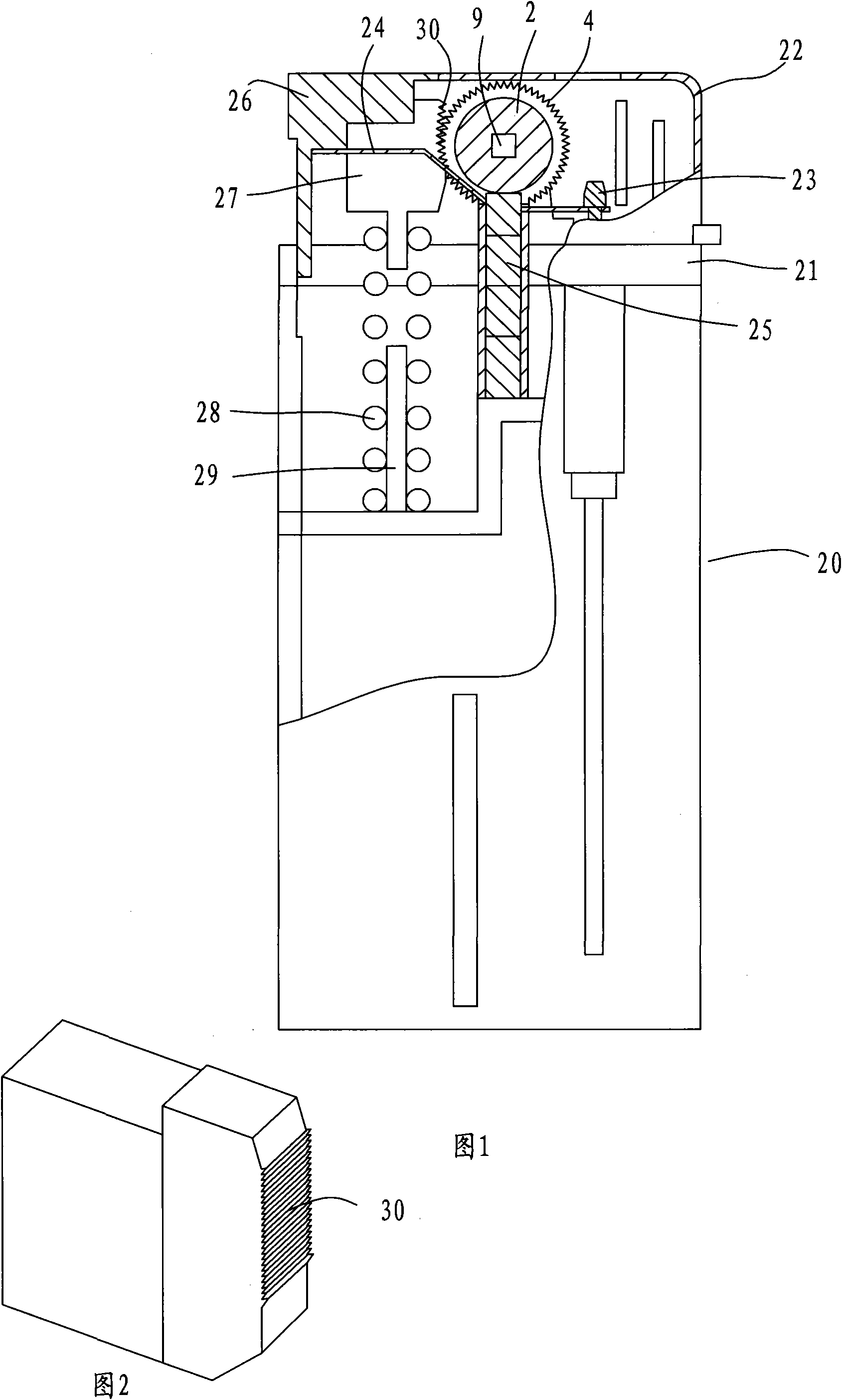
[0036] Embodiment 1, combining Figure 1 to Figure 8 , a lighter, comprising a shell 20, a head frame 21, a windshield 22, an air outlet needle 23, a lever 24, a fire wheel assembly, a flint 25, a button 26, a gear block 27 and a return spring 28, and a return spring 28 The bottom end is put on the positioning column 29, the top of the return spring is installed on the bottom of the gear block 27, the gear block 27 is pressed against the button 26 through the return spring, one end of the warping rod 24 is stuck on the air outlet needle 23, and the other end is matched with the button 26 And link with it. Button 26 presses down, and the warping bar 24 end that cooperates with button 26 moves down, and the other end of warping bar 24 moves up as a lever, lifts gas outlet needle 23, makes liquefied gas can be ejected from gas outlet needle 23 places.

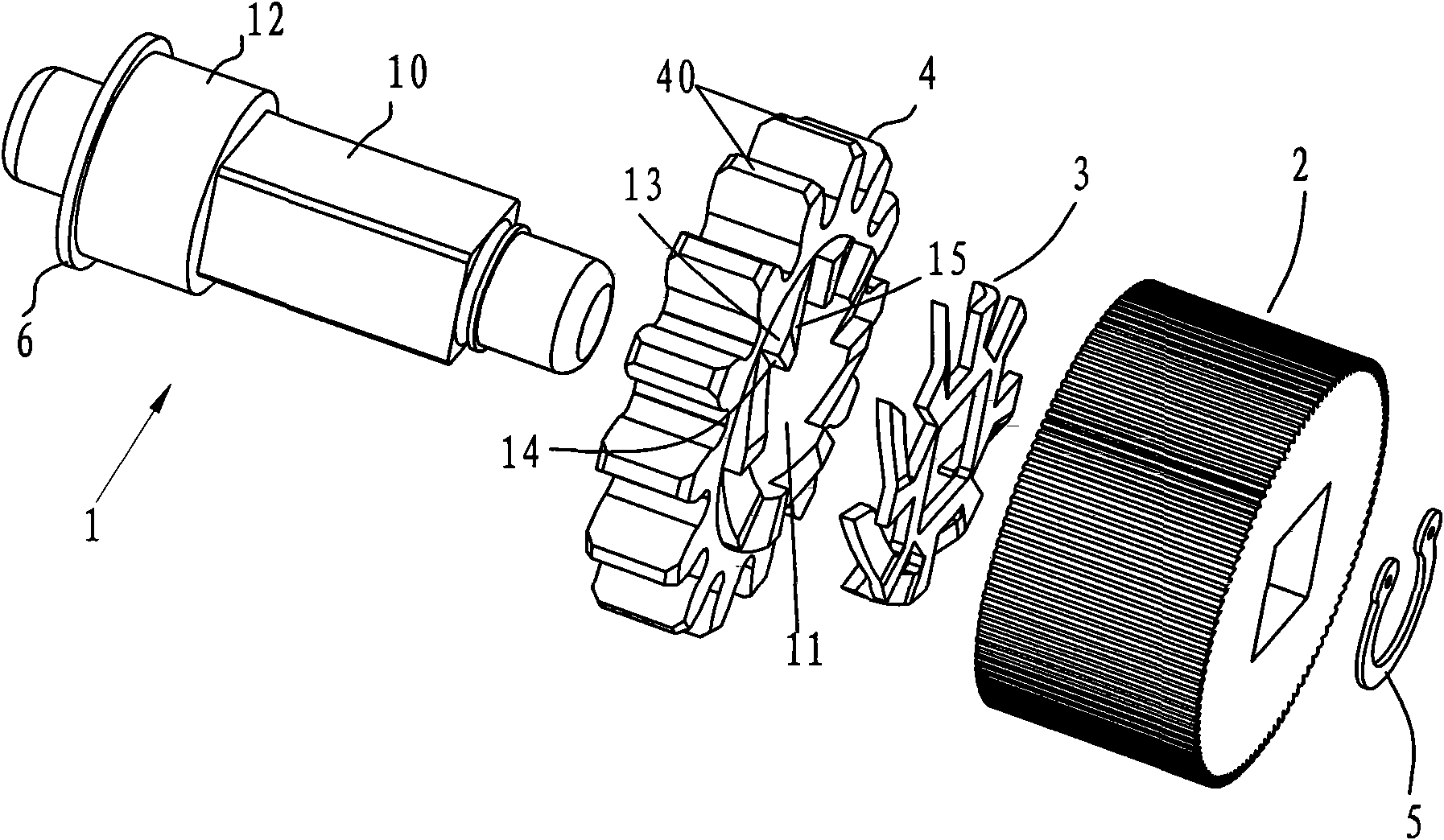
[0037] The fire wheel assembly includes a rotating shaft 1, a fire wheel 2, a transmission shrapnel 3 and a side wheel 4, the f...

Embodiment 2

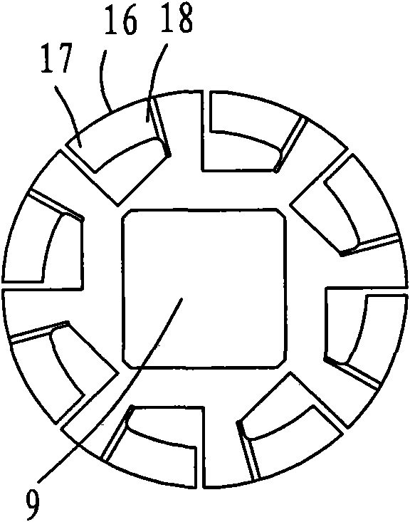
[0040] Example 2, combined with Figure 9 to Figure 17 , the difference between embodiment 2 and embodiment 1 is mainly in the ignition wheel assembly, the structure of the ignition wheel assembly in embodiment 2 is: including the rotating shaft 1, the ignition wheel 2, two transmission shrapnel 3, 3' and two side wheels 4, 4', the ignition wheel 2, the transmission shrapnel and the side wheel are all worn on the shaft 1, and the outer surface of the ignition wheel 2 and the side wheel 4 is provided with a clamping device 5, 6 to prevent the ignition wheel and the side wheel from moving axially along the shaft . Above-mentioned rotating shaft 1 also can be by Figure 16 Rotating shaft 1 ' in the middle replaces, and rotating shaft 1 ' is divided into two sections, and the opposite ends of two sections of rotating shafts are respectively inserted in the firing wheel body, realize connection by firing wheel.

[0041] The two sides of the firing wheel facing the transmission sh...


PUM


Abstract

The invention relates to a lighter which lights through friction between an ignition wheel and a firestone. The lighter comprises a shell, a head frame, a wind shield cover, an air outlet needle, a protruding rod, an ignition wheel assembly, the firestone, a button, a gear block and a return spring, wherein the ignition wheel assembly comprises a rotating shaft, and the ignition wheel, a transmission elastic sheet and an edge wheel which are sleeved on the rotating shaft; the transmission elastic sheet is arranged between the ignition wheel and the edge wheel; the transmission elastic sheet, the ignition wheel and the rotating shaft are in transmission fit with one another; the edge wheel and the rotating shaft are in running fit with each other; the side face of the edge wheel facing the transmission elastic sheet is provided with a plurality of connecting teeth around an axle hole of the edge wheel; the plurality of connecting teeth are arranged around the axle hole in a circle shape; and each connecting tooth is provided with a hooking surface and a sloping surface. The lighter has a simple and reasonable structural design; the transmission elastic sheet is added between the edge wheel and the ignition wheel, so that the problems that the lighter cannot perform transmission reliably during lighting, the side wheel cannot be quickly reset during extinguishing, and the like are well solved; and the structure of the lighter is greatly simplified, so that the lighter is labor-saving during the lighting.

Description

technical field [0001] The invention relates to a lighter which is ignited by friction between a fire wheel and a flint. Background technique [0002] Now there are two ways to start a lighter. One is a mechanical lighter that is lit by friction between the fire wheel and the flint. The mechanical lighter is to press the side wheel and the fire wheel tightly by hand and force it to rotate to achieve ignition. This kind of ignition mode is inconvenient and laborious. The other is an electronic lighter that ignites through piezoelectric ceramics. The electronic lighter is easy to ignite and does not make the hand smelly. For this reason, the applicant has previously applied for an invention patent, the application number is 200910115330.4. This application realizes that the mechanical lighter can be ignited without directly rotating the side wheel and the ignition wheel by hand, and only needs to be lightly pressed by hand. Press the button, press the gear block through the ...

Claims


Application Information

Patent Timeline
Patent Type & Authority Applications(China)
IPC IPC(8): F23Q2/16F23Q2/46
Inventor 杨文森
Owner 杨文森
Why Eureka
Try Eureka