Metal and conductive plastic composite micro heat exchanger
A technology of heat-conducting plastics and micro-heat exchangers, which is applied in the direction of indirect heat exchangers, heat exchanger types, semiconductor devices, etc., can solve the problems of large heat exchangers, large consumption of fin metal materials, and poor compactness. Achieve high thermal conductivity, fast heat transfer and good processability
- Summary
- Abstract
- Description
- Claims
- Application Information
AI Technical Summary
Problems solved by technology
Method used
Image
Examples
Embodiment 1
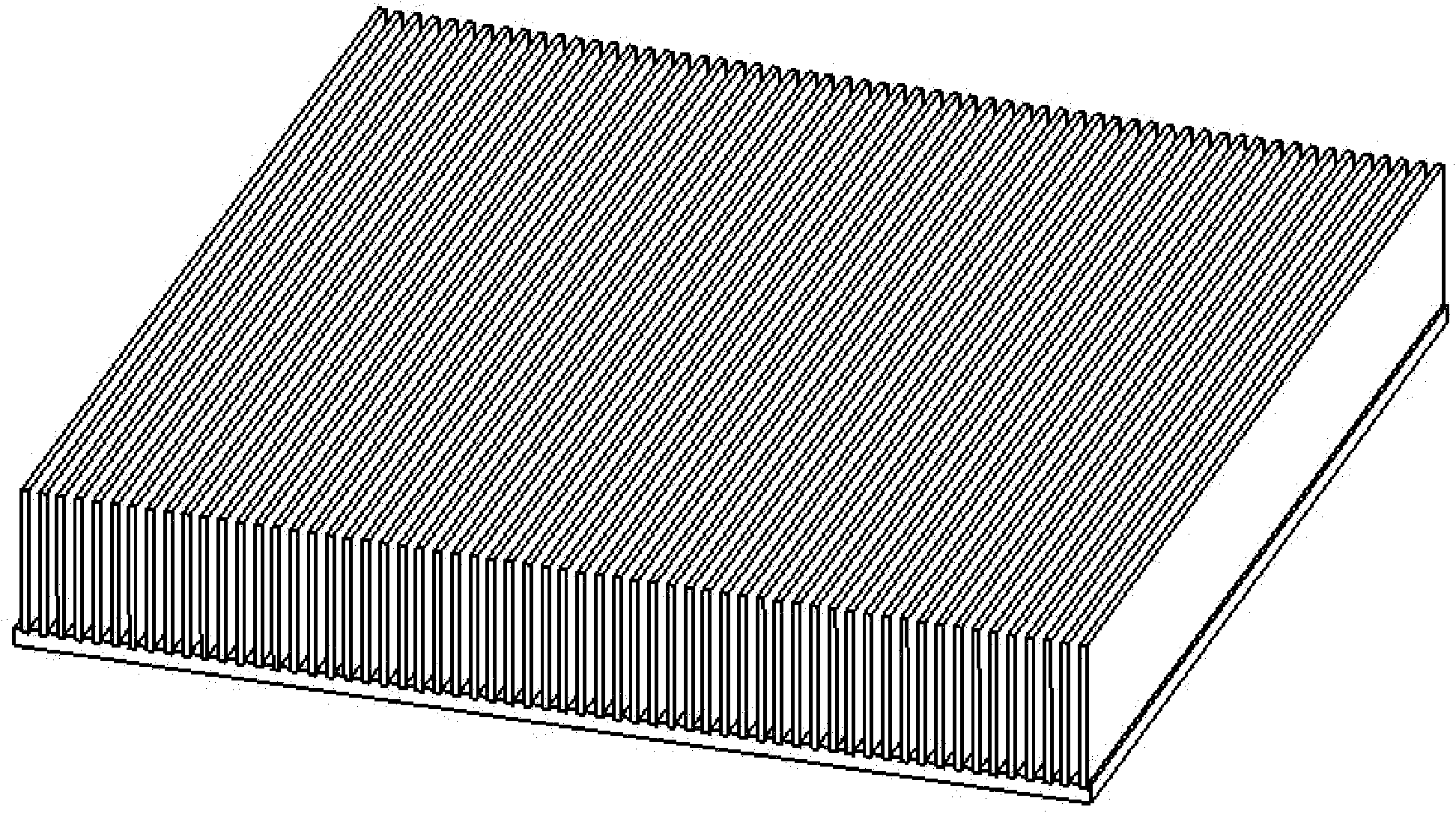
[0022] refer to figure 1 , a finned heat sink with a plastic microstructure that can be used as a heat sink for heat-generating electronic devices. This embodiment is composed of a metal substrate 1 and a composite high thermal conductivity plastic microstructure 2, and the microstructure 2 is a miniature thermal conductivity plastic fin compounded on the metal surface. figure 1 The metal substrate is made of thick 1×60×60mm aluminum sheet, and the fins are made of 0.2×8×60mm CoolPoly heat-conducting plastic, with the spacing between fins being 0.4mm. figure 2 It is a partially enlarged view. Experiments show that under the same heating power, the heat exchange effect of the present invention is close to that of conventional aluminum fins. This embodiment is applied to the case where the surrounding of the heat exchanging fins is gas.
Embodiment 2
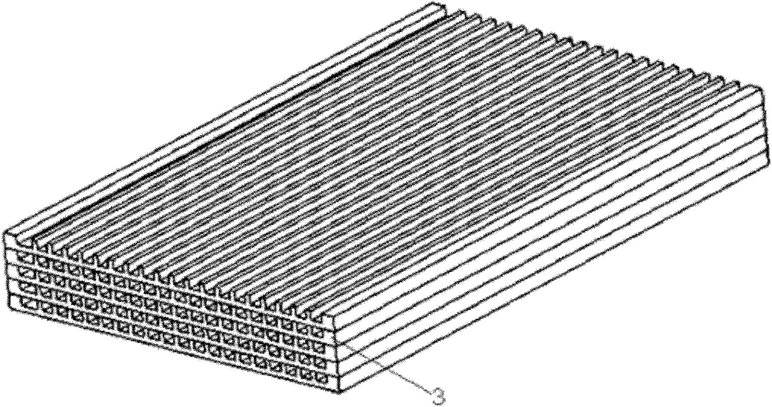
[0024] refer to image 3 , a flat plate heat exchanger with plastic microchannels. In this embodiment, composite thin plates with wide and flat microchannels are connected and stacked together by diffusion bonding, and cold and hot fluids alternately flow through these thin plates, and heat exchange is realized through both sides of the thin plate walls. Refer to the internal structure of the heat exchanger image 3 , the flat plate is a 2×40×60mm composite board, including a copper substrate 4 and a CoolPoly heat-conducting plastic rectangular fin 5 compounded on the copper substrate (see the specific structure diagram of the flat plate Figure 4 ), the size of the fins is 0.2×1.2×60mm, which are arranged on the plate in sequence to form a fluid microchannel with a width of 0.5mm. The fins are processed on the plate surface by micro-injection to form the channel space for dividing the main fluid. The multi-layer composite plates are stacked together to form a cubic multi-la...
PUM
 Abstract
Description
Claims
Application Information
 - R&D
- Intellectual Property
- Life Sciences
- Materials
- Tech Scout
- Unparalleled Data Quality
- Higher Quality Content
- 60% Fewer Hallucinations
Browse by: Latest US Patents, China's latest patents, Technical Efficacy Thesaurus, Application Domain, Technology Topic, Popular Technical Reports.
© 2025 PatSnap. All rights reserved.Legal|Privacy policy|Modern Slavery Act Transparency Statement|Sitemap|About US| Contact US: help@patsnap.com


