Laser planeness detector

A flatness detection and laser technology, used in instruments, measuring devices, optical devices, etc., can solve problems such as exceeding, and achieve the effect of large size, improved detection range and detection speed

Inactive Publication Date: 2011-06-29
INST OF OPTICS & ELECTRONICS - CHINESE ACAD OF SCI
View PDF0 Cites 25 Cited by
  • Summary
  • Abstract
  • Description
  • Claims
  • Application Information

AI Technical Summary

Problems solved by technology

The first two methods can only detect continuous planes, and cannot be used for detection of discontinuous planes (with holes, grooves, bosses in the middle, interruptions in the middle, and special-shaped planes)
The three-coordinate measurement method is the best method for measuring the flatness of discontinuous planes, but in the current large-scale equipment, the size of the large workpiece is far beyond the measurement range of the three-coordinate

Method used


Image

  • Laser planeness detector
  • Laser planeness detector
  • Laser planeness detector

Examples


Embodiment Construction

[0017] In order to make the object, technical solution and advantages of the present invention clearer, the present invention will be described in further detail below in conjunction with specific embodiments and with reference to the accompanying drawings.

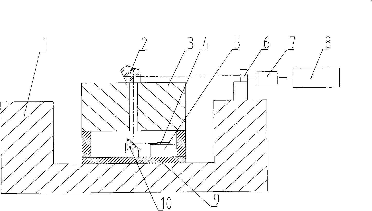
[0018] Such as figure 1 As shown, the specific implementation of the laser flatness detector is:

[0019] It consists of a pentaprism 2, a turntable 3, a laser 4, a four-dimensional workbench 5, a PSD position sensor 6, a data acquisition unit 7, a data processing unit 8, a base 9 and a plane mirror 10; placed in the middle of the bottom of the base 9 Plane reflector 10, four-dimensional workbench 5 is placed at the bottom and side of base 9, laser 4 is fixed on four-dimensional workbench 5, turntable 3 has a center hole, and pentaprism 2 is placed at turntable 3 center hole positions On the working surface, the reference plane formed by the outgoing light of the pentaprism 2 rotated with the turntable 3 is always perpen...


PUM


Abstract

The invention relates to a laser planeness detector, consisting of a pentaprism, a rotary platform, a laser, a four-dimensional working platform, a PSD (Position Sensitive Detector) position sensor, a computer data acquisition unit, a data processing unit, a base and a planar reflecting mirror, wherein light emitted by the laser is ejected horizontally after passing through the center of the rotary platform and being reflected by the pentaprism. The pentaprism rotates along with the rotary platform, and laser which is ejected horizontally by the pentaprism also rotates along the rotary platform; and the horizontal laser beams rotate to form a reference plane. The PSD position sensor is placed on the measured plane, so that the height difference between a measured point and the reference plane formed by the laser beams can be measured, the planeness error of a detected plane can be obtained after data processing.

Description

technical field [0001] The invention relates to a flatness tester, in particular to a flatness test for large discontinuous planes. Background technique [0002] The flatness detection methods of large parts include electronic level meter-bridge method, three-point support method (mainly used for circular planes) and three-coordinate measurement method. The first two methods can only detect continuous planes, and cannot be used for the detection of discontinuous planes (with holes, grooves, bosses in the middle, discontinuities in the middle, and special-shaped planes). The three-coordinate measurement method is the best method for measuring the flatness of discontinuous planes, but in the current large-scale equipment, the size of the large workpiece is far beyond the measurement range of the three-coordinate. Therefore, the research on flatness measurement methods of large planes, circular rings and discontinuous planes has been carried out, and a new type of measuring de...

Claims


Application Information

Patent Timeline
Patent Type & Authority Applications(China)
IPC IPC(8): G01B11/30
Inventor 曹学东杨文志景洪伟许玮琦
Owner INST OF OPTICS & ELECTRONICS - CHINESE ACAD OF SCI
Why Eureka
Try Eureka