Field assembly method for transformer

A technology for on-site assembly and transformers, applied in the manufacture of inductors/transformers/magnets, electrical components, circuits, etc., can solve problems such as the overweight of the converter transformer body, the difficulty of transporting the UHV converter transformer, etc.

Active Publication Date: 2011-06-29
STATE GRID CORP OF CHINA
View PDF4 Cites 12 Cited by
  • Summary
  • Abstract
  • Description
  • Claims
  • Application Information

AI Technical Summary

Problems solved by technology

With the increase of power and voltage level in the UHV DC transmission project, the capacity of a single converter transformer is getting higher and higher, which makes the transpo

Method used


Image

  • Field assembly method for transformer
  • Field assembly method for transformer
  • Field assembly method for transformer

Examples


Example Embodiment

[0035] Various exemplary embodiments of the present invention will now be described in detail with reference to the accompanying drawings. It should be noted that unless specifically stated otherwise, the relative arrangement of components and steps, numerical expressions and numerical values ​​set forth in these embodiments do not limit the scope of the present invention.

[0036] The following description of at least one exemplary embodiment is actually only illustrative, and in no way serves as any limitation to the present invention and its application or use.

[0037] The technologies, methods, and equipment known to those of ordinary skill in the relevant fields may not be discussed in detail, but where appropriate, the technologies, methods, and equipment should be regarded as part of the authorization specification.

[0038] In all the examples shown and discussed herein, any specific value should be interpreted as merely exemplary and not as limiting. Therefore, other examp...


PUM


Abstract

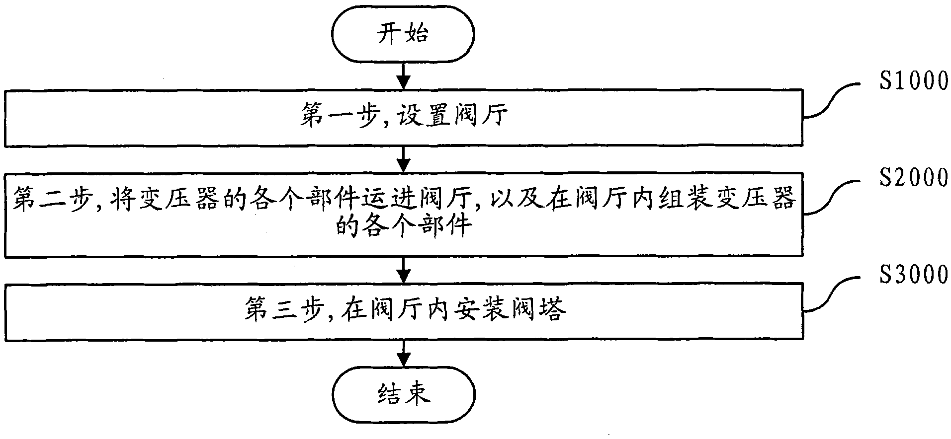
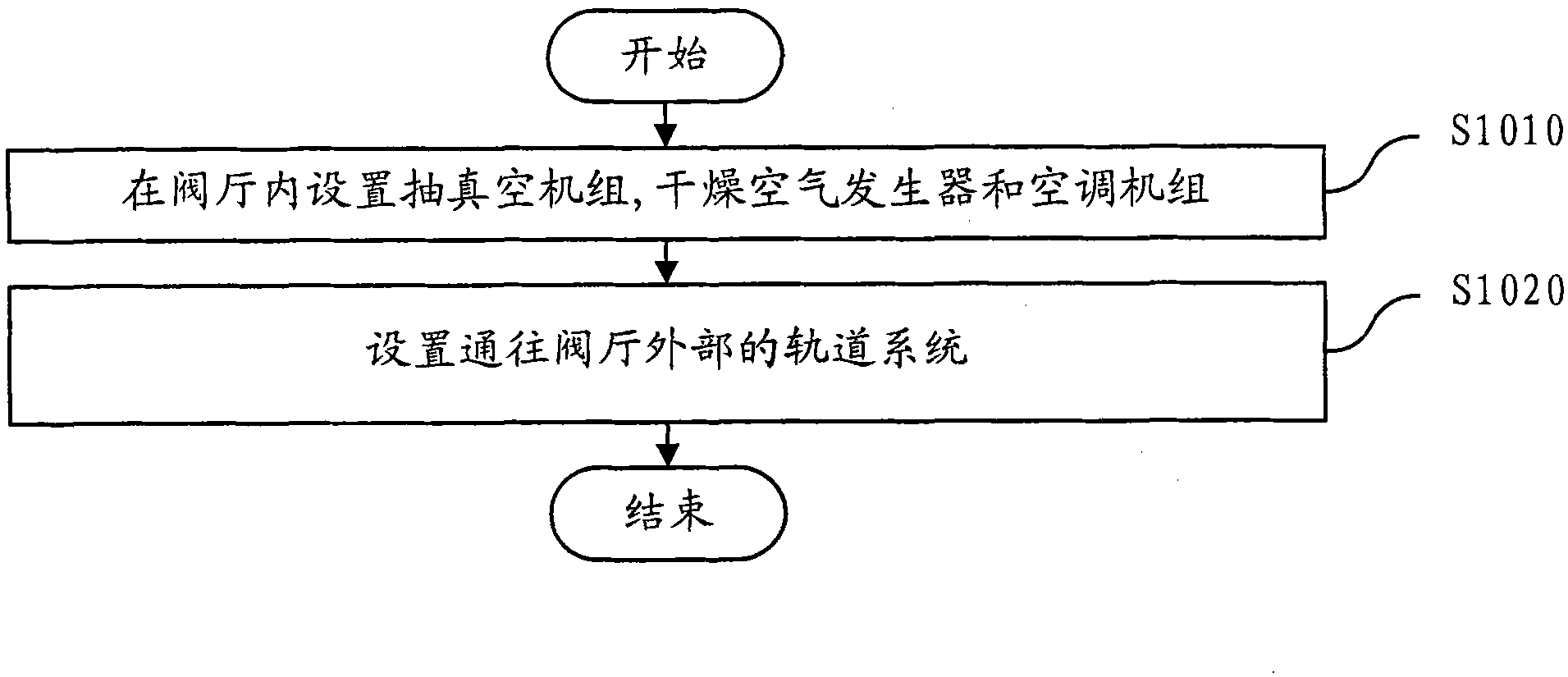
The invention discloses a field assembly method for a transformer. The method comprises the following steps of: 1, arranging a valve hall; 2, conveying each component of the transformer into the valve hall and assembling each component of the transformer in the valve hall; and 3, mounting a valve tower in the valve hall.

Description

technical field [0001] The invention relates to the technical field of transformer assembly in power transmission engineering, in particular to a transformer field assembly method. Background technique [0002] The research and application of UHV DC transmission technology has broad development space and application prospects. With the increase of power and voltage levels in UHVDC transmission projects, the capacity of a single converter transformer is also getting higher and higher, which makes the transportation of UHV converter transformers difficult. The main transportation difficulty of the known UHV converter transformers is the overweight and over-limit problems of the converter transformer body. The overweight problem is reflected in the transportation of the iron core, and the over limit problem is reflected in the external dimensions of the fuel tank. [0003] In the prior art, an Advanced Site Assembly (ASA) transformer is used to solve the transportation proble...

Claims


Application Information

Patent Timeline
IPC IPC(8): H01F41/00
Inventor 孙昕
Owner STATE GRID CORP OF CHINA
Why Eureka
Try Eureka