A method and device for supplementing light in a camera
A light supplement and camera technology, applied in the field of camera supplement light, can solve the problems of high power requirements, uncontrollable exposure time or limited power consumption, etc., to achieve the effect of reducing power consumption
- Summary
- Abstract
- Description
- Claims
- Application Information
AI Technical Summary
Problems solved by technology
Method used
Image
Examples
Embodiment 1
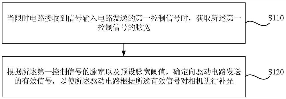
[0040] figure 1 It is a schematic flow chart of a method for supplementing light for a camera provided by Embodiment 1 of the present invention. The embodiment of the present invention is applicable to the situation of supplementing light for a camera. This method can be performed by a camera supplementing light device, which can Realized in the form of software and / or hardware.
[0041] Such as figure 1 Described, the method of the embodiment of the present invention comprises:
[0042] S110. When the time-limiting circuit receives the first control signal sent by the signal input circuit, acquire the pulse width of the first control signal.
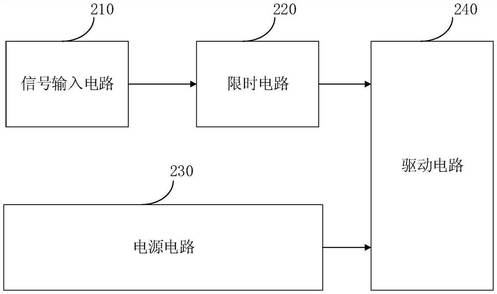
[0043] Wherein, the circuit corresponding to the method for implementing the camera light supplement can be referred to as a camera supplement light circuit. see figure 2 , the camera supplementary light circuit 20 includes: a signal input circuit 210 , a time limit circuit 220 , a power supply circuit 230 and a drive circuit 240 ....
Embodiment 2
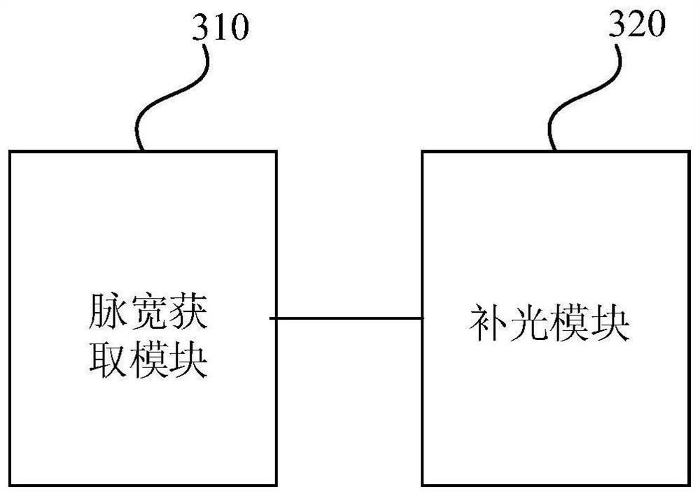
[0067] image 3 It is a schematic structural diagram of a device for supplementary light for cameras provided by Embodiment 2 of the present invention. The device may have a signal input circuit, a display circuit, a power supply circuit and a driving circuit configured inside it to realize its specific functions. The supplementary light device of the device includes: a pulse width acquisition module 310 and a supplementary light module 320 .
[0068] The pulse width acquisition module 310 is used to acquire the pulse width of the first control signal when the time-limiting circuit receives the first control signal sent by the signal input circuit; the supplementary light module 320 is used to obtain the pulse width according to the first control signal The pulse width and the preset pulse width threshold determine the effective signal sent to the driving circuit, so that the driving circuit performs supplementary light on the camera according to the effective signal.
[0069...
Embodiment 3
[0086] Figure 4 It is a schematic structural diagram of a device provided by Embodiment 3 of the present invention. Figure 4 A block diagram of an exemplary apparatus 40 suitable for implementing an embodiment of the invention is shown. Figure 4 The shown device 40 is only an example, and should not impose any limitation on the functions and scope of use of the embodiments of the present invention.
[0087] Such as Figure 4 As shown, device 40 takes the form of a general purpose computing device. Components of the device 40 may include, but are not limited to: one or more processors or processing units 401 , a system memory 402 , and a bus 403 connecting different system components (including the system memory 402 and the processing unit 401 ).
[0088] Bus 403 represents one or more of several types of bus structures, including a memory bus or memory controller, a peripheral bus, an accelerated graphics port, a processor, or a local bus using any of a variety of bus stru...
PUM
 Abstract
Description
Claims
Application Information
 - R&D
- Intellectual Property
- Life Sciences
- Materials
- Tech Scout
- Unparalleled Data Quality
- Higher Quality Content
- 60% Fewer Hallucinations
Browse by: Latest US Patents, China's latest patents, Technical Efficacy Thesaurus, Application Domain, Technology Topic, Popular Technical Reports.
© 2025 PatSnap. All rights reserved.Legal|Privacy policy|Modern Slavery Act Transparency Statement|Sitemap|About US| Contact US: help@patsnap.com


