Omnidirectional wideband high gain antenna

A high-gain antenna and broadband technology, applied in the field of antennas, can solve the problems of large size, unsuitable binary array antenna, influence of antenna radiation characteristics, etc., to achieve the effect of broadening impedance bandwidth and pattern bandwidth

Inactive Publication Date: 2011-06-29
XIDIAN UNIV
View PDF2 Cites 19 Cited by
  • Summary
  • Abstract
  • Description
  • Claims
  • Application Information

AI Technical Summary

Benefits of technology

This patented design allows an improved compact radar system by improving the performance of the radio wave transmitting device (RF). It achieves this through combining multiple cones or other types of resonant elements into one larger component called a phantom body. By having both conic and disk components instead of only one element, it becomes possible to achieve wider range of frequencies without increasing their size. Additionally, the use of a helix stub connecting the top and bottom parts makes it easy to route cables from the radome's main circuitry back towards the user terminal. Overall, these technical improvements improve the efficiency and effectiveness of the radar systems while reducing weightiness.

Problems solved by technology

The technical problem addressed in this patents relating to wireless communications involves achieving both high efficiency (small) and compactness while also maintaining good performance under various conditions including varying operating environments like temperature, humidity, rainwater level, wave height, orientation angle, and altitude. Additionally, reducing noise emissions during use without compromising signal reception ability at specific locations within these ranges becomes necessary due to limitations associated with current designs involving multiple antennas mounted sideways around a vehicle body frame.

Method used


Image

  • Omnidirectional wideband high gain antenna
  • Omnidirectional wideband high gain antenna
  • Omnidirectional wideband high gain antenna

Examples


Embodiment Construction

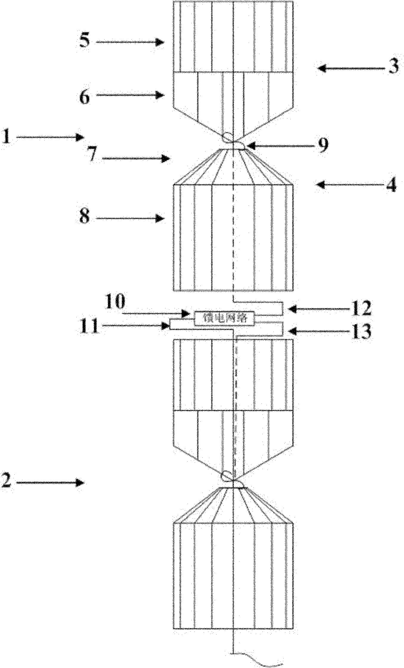
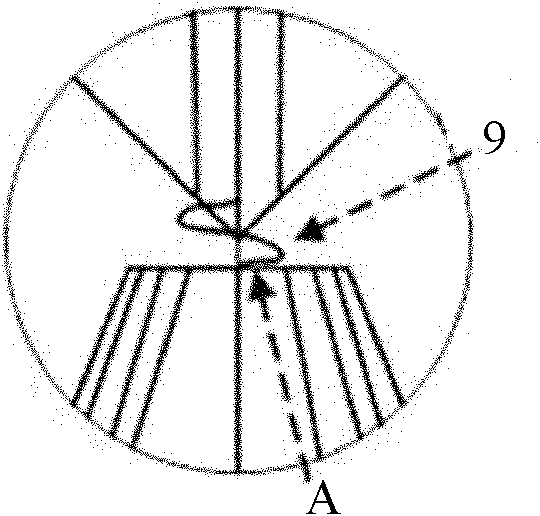
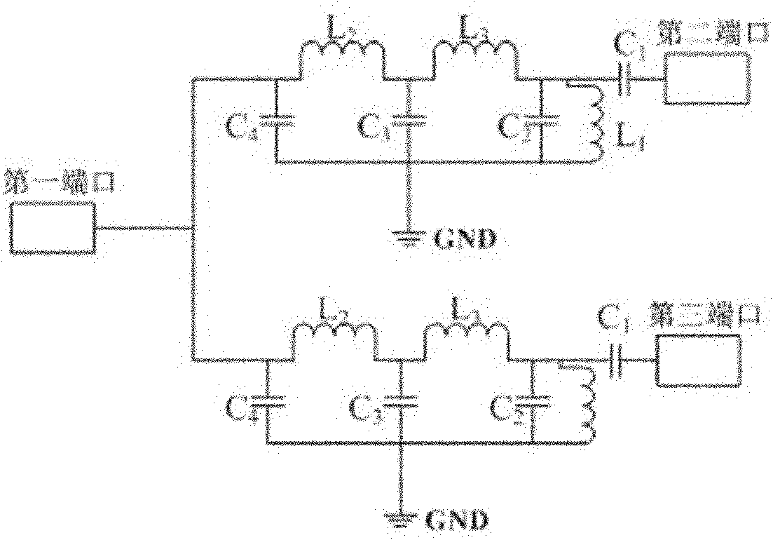
[0021] refer to figure 1 , the omnidirectional broadband high-gain antenna given in this embodiment is composed of two identical radiating units 1 and 2 and a feeding network 10, and the entire antenna works at 100-400 MHz. Both the radiation unit 1 and the radiation unit 2 are wire grid structures welded by copper wires. Each radiating unit is composed of two upper and lower cone vibrators with different structures. The upper cone vibrator 3 adopts a composite structure with a cylinder 5 and a disc cone 6 at the bottom. The cylinder 5 is welded by 16 copper wires, and the disc cone 6 is Four gradually changing trapezoidal surfaces, disc cone 6 and cylinder 5 are of the same height; the lower cone vibrator 4 adopts a composite structure in which the upper part is a circular platform 7 and the lower part is a cylinder 8. The circular platform 7 is welded by copper wires. The radius of the lower bottom surface of the circular platform 7 is The radius of the bottom surface of th...


PUM


Abstract

The invention discloses an omnidirectional wideband high gain antenna which is mainly used for solving the problem that the communication quality at high frequency is reduced owing to fission or upwarping of a directional pattern at the high frequency end of a dipole antenna along with the increasing of frequency in short wave/ultra short wave mobile communication of vehicles, naval vessels and the like. The whole antenna comprises two identical radiating elements (1 and 2) and a wideband feed network (10), wherein each radiating element consists of upper and lower cone oscillators of different structures; the upper cone oscillator (3) is of a composite structure with a cylinder (5) at the upper part and a discone (6) at the lower part; the lower cone oscillator (4) is of a composite structure with a circular truncated cone (7) at the upper part and a cylinder (8) at the lower part; and the upper and lower cone oscillators are connected through spiral stubs (9). The whole antenna works within a 100-400MHz frequency range, the impedance bandwidth and directional pattern bandwidth of the antenna are widened in the working frequency range, and the omnidirectional radiation in the horizontal direction and maximum gain in the horizontal direction of the antenna can be realized.

Description


Claims


Application Information

Patent Timeline
Owner XIDIAN UNIV
Why Eureka
Try Eureka