

Improved Fabry-Perot resonant cavity antenna
An improved technology for resonant cavity antennas, applied in the field of resonant cavity antennas, can solve the problem of low gain bandwidth and achieve the effects of increased gain, impedance bandwidth and gain bandwidth
- Summary
- Abstract
- Description
- Claims
- Application Information
AI Technical Summary
Problems solved by technology
Method used
Image

Examples
specific Embodiment approach 1
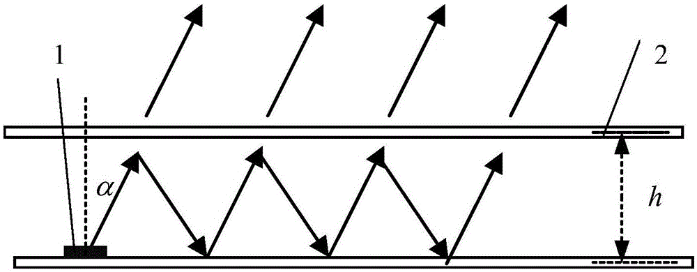
[0033] Specific implementation mode one: the following combination Figure 1 to Figure 3 Describe this embodiment, the improved Fabry-Pérot resonant cavity antenna described in this embodiment, it comprises feed source 1 and partial reflector 2,
[0034] The feed source 1 is a rectangular patch antenna, and a part of the reflector 2 is placed in parallel above the feed source 1, and the height of the resonant cavity formed between the feed source 1 and the part of the reflector 2 is h;
[0035] Part of the reflector 2 is a double-sided coating structure, the upper surface of which is a periodically arranged copper-clad array, and the lower surface is a periodically arranged hollow cross-shaped copper-clad square array;
[0036] The method that makes described resonant cavity antenna obtain maximum gain is:
[0037] Let the directivity function of the feed 1 be f(α), and the reflection coefficient of the partial reflector 2 be The transmission coefficient is The reflection...
specific Embodiment approach 2
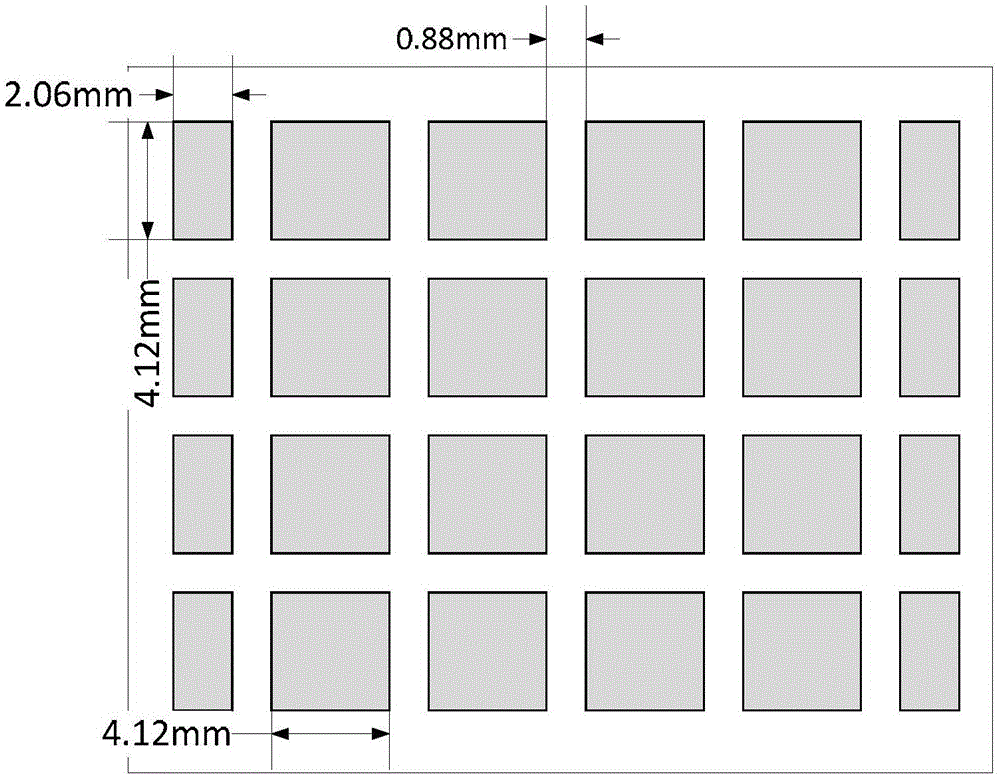
[0053] Specific implementation mode two: the following combination image 3 Describe this embodiment, this embodiment will further explain Embodiment 1, in the copper clad array on the upper surface of the partial reflector 2, the side length of all the square copper clad in the middle row of copper clad is 4.12mm, all the copper clad in the copper clad array The mutual spacing is 0.88mm.
specific Embodiment approach 3
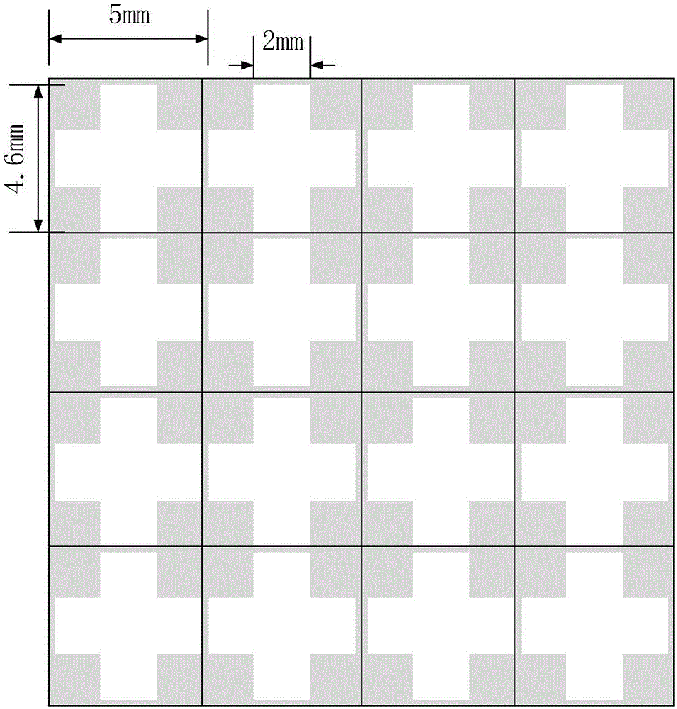
[0054] Specific implementation mode three: the following combination Figure 1 to Figure 7 Describe this embodiment mode, this embodiment mode will further explain Embodiment 2, in the hollow cross-shaped copper clad square array on the lower surface of the partial reflector 2, the side length of each period is 5 mm, and the cross length of the hollow cross shape is 4.6mm, the width of the hollow cross is 2mm.
[0055]Each periodic unit of the lower surface of the partial reflection plate 2 is a small square of a dielectric plate of 5 mm×5 mm, a relative permittivity of 1.5, and a thickness of 1.5 mm.
PUM
| Property | Measurement | Unit |
|---|---|---|
| Thickness | aaaaa | aaaaa |
| Impedance bandwidth | aaaaa | aaaaa |
| Center frequency | aaaaa | aaaaa |
Abstract
Description
Claims
Application Information