LTCC aperture coupling array antenna

A technology of coupling arrays and slots, applied in the direction of antennas, antenna arrays, antenna grounding devices, etc., can solve the unfavorable development needs of microstrip patch antennas and carrier conformal design miniaturization, increase the thickness or area of ​​antennas, etc. Achieve the effect of increasing bandwidth, improving stability and reliability, and closely arranged

Inactive Publication Date: 2015-06-24
UNIV OF ELECTRONICS SCI & TECH OF CHINA
View PDF6 Cites 16 Cited by
  • Summary
  • Abstract
  • Description
  • Claims
  • Application Information

AI Technical Summary

Problems solved by technology

However, these methods are at the expense of increasing the thickness or area of ​​the antenna, which is not conducive to the conformal design of the microstrip patch antenna and the carrier and the development needs of miniaturization
The contradiction between miniaturization, broadband and high-gain development of microstrip patch antenna has not been well resolved

Method used


Image

  • LTCC aperture coupling array antenna
  • LTCC aperture coupling array antenna
  • LTCC aperture coupling array antenna

Examples


Embodiment

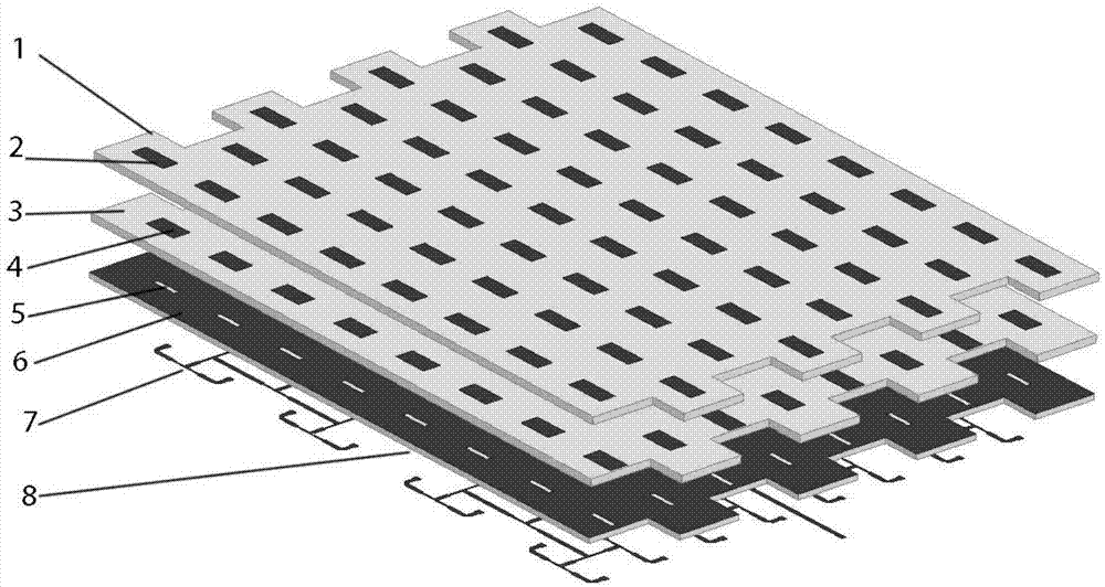
[0028] This embodiment provides a LTCC slot-coupled broadband high-gain microstrip array antenna with a center frequency of 10 GHz, and its structure is as follows Figure 1 to Figure 5 As shown, it mainly includes:

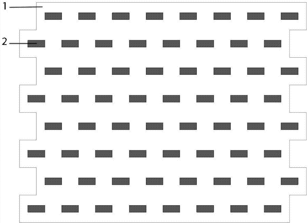
[0029] The upper dielectric substrate 1 is made of 15 LTCC cast film sheets with a thickness of 0.1mm and a dielectric constant of 5.9. The upper surface is printed with silver paste and has 64 upper-layer radiation metals arranged in a triangular grid. SMT unit 2;

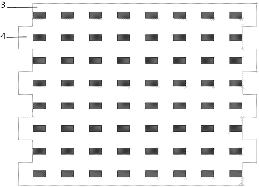
[0030] The middle dielectric substrate 3 is formed by laminating 15 LTCC cast film sheets with a thickness of 0.1mm and a dielectric constant of 5.9, and its upper surface is 64 lower radiation metal patch units arranged in a rectangular grid 4 ;

[0031] The lower dielectric substrate 8 is formed by stacking five LTCC cast film sheets with a thickness of 0.1mm and a dielectric constant of 5.9. The paste is printed with a grounded metal layer 6, and 64 resonant slots 5 are opened on the grounded me...


PUM


Abstract

The invention provides an LTCC aperture coupling array antenna, belongs to the technical field of antennas and aims at overcoming the defects of an existing micro-strip array antenna in the aspect of giving consideration to miniaturization, broadband and high gain. The LTCC aperture coupling array antenna comprises upper and lower layer radiation metal patch units, upper, middle and lower layer dielectric substrates, a grounded metal layer, resonance apertures and a micro-strip feed network, wherein the upper layer radiation metal patch units are arranged in triangular lattices, and the lower radiation metal patch units are arranged in rectangular lattices. Compared with regular micro-strip patch array antennas based on organic media or ceramic substrates, the LTCC aperture coupling array antenna is capable of obtaining a larger antenna bandwidth under the same size limit and giving better consideration to the performance requirements of miniaturization, broadband and high gain of the patch antenna.

Description

technical field [0001] The invention belongs to the technical field of antennas, in particular to an LTCC wide-band high-gain array antenna. Background technique [0002] Microstrip patch antenna has many advantages such as small size, light weight, thin profile, easy conformal, etc. It is widely used in radar, missile measurement and control, satellite positioning, wireless communication, remote sensing, aerospace and other fields. In airborne or missile-borne applications, the performance requirements of microstrip array antennas are particularly emphasized for their miniaturization, wide frequency band and high gain. However, the input impedance of the microstrip patch antenna is very sensitive to changes with frequency, resulting in a narrow impedance bandwidth. The current microstrip patch antennas generally use organic dielectric materials or ceramic materials as substrates. In order to expand the bandwidth of microstrip patch antennas, common methods include increasi...

Claims


Application Information

Patent Timeline
Patent Type & Authority Applications(China)
IPC IPC(8): H01Q1/38H01Q1/48H01Q1/50H01Q21/00
Inventor 张怀武李贵栋李丽君郝欣欣段耀铎刘小飞
Owner UNIV OF ELECTRONICS SCI & TECH OF CHINA
Why Eureka
Try Eureka