MEMS microphone and manufacturing method thereof

A technology of microelectronic machinery and manufacturing method, applied in the direction of electrostatic transducer microphone, sensor, semiconductor electrostatic transducer, etc., can solve the problem of microphone limitation, and achieve the effect of stable acoustic characteristics, easy formation, and deformation prevention.

Inactive Publication Date: 2015-12-09
BSE CO LTD
View PDF4 Cites 0 Cited by
  • Summary
  • Abstract
  • Description
  • Claims
  • Application Information

AI Technical Summary

Problems solved by technology

Therefore, there is a limit to the manufacture of miniaturized microphones

Method used


Image

  • MEMS microphone and manufacturing method thereof
  • MEMS microphone and manufacturing method thereof
  • MEMS microphone and manufacturing method thereof

Examples


Embodiment Construction

[0042] A specific embodiment of the MEMS microphone of the present invention to achieve the above object will be described.

[0043] A first embodiment of the MEMS microphone of the present invention will be described.

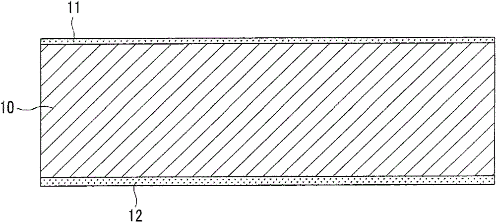
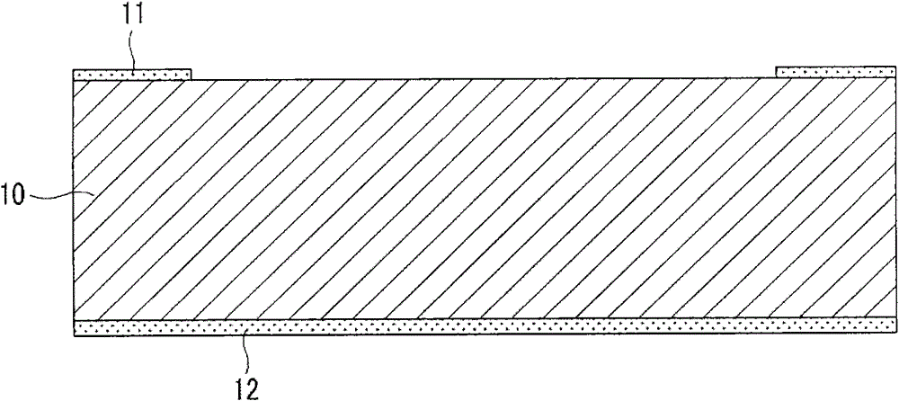
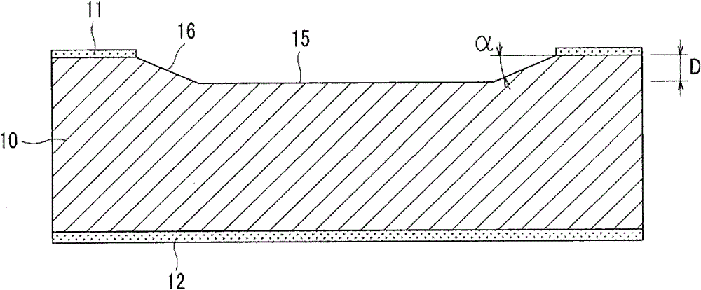
[0044] Figure 1a to Figure 1c It is a cross-sectional view showing a step of forming a void forming portion on a silicon substrate in the first embodiment of the MEMS microphone of the present invention.

[0045] refer to Figure 1a and Figure 1b , the MEMS microphone includes a silicon substrate 10 . On both sides of the silicon substrate 10, silicon nitride (Si 3 N 4 ) or silicon oxide (SiO 2) and other insulating protective layers 11, 12 (refer to Figure 1a ). At this time, the silicon nitride is vapor-deposited with protective layers 11 and 12 on the surface of the silicon substrate 10 by Low Pressure Chemical Vapor Deposition (LPCVD: Low Pressure Chemical Vapor Deposition).

[0046] The insulating protective layer 11 on the upper side of the si...


PUM

PropertyMeasurementUnit
thicknessaaaaaaaaaa
thicknessaaaaaaaaaa

Abstract

The present invention relates to a MEMS microphone having less residual stress at a contact portion between a silicon substrate and a membrane, and to a method for manufacturing the MEMS microphone. The MEMS microphone comprises: a silicon substrate in which a back chamber is formed; a back plate deposited on the silicon substrate and including a plurality of sound holes; a membrane deposited on the silicon substrate and spaced apart from the back plate to form an air gap; and a stress buffer deposited between the membrane and the silicon substrate.

Description

technical field [0001] The invention relates to a micro-electro-mechanical system microphone and a manufacturing method thereof. Background technique [0002] In general, a microphone is a device that converts sound into electrical signals. The microphone is used in various communication devices, such as mobile communication devices such as mobile terminals, earphones or hearing aids. Such microphones should have good electronic / acoustic performance, reliability and workability. [0003] The microphone includes a condenser microphone, a MEMS microphone, and the like. [0004] The condenser microphone is manufactured by separately manufacturing a vibration plate, a support plate, and a printed circuit board for signal processing, etc., and then assembling the structure inside the case. Since the process of manufacturing the printed circuit board and the process of manufacturing the condenser microphone are separated in such a condenser microphone, the production cost incre...

Claims


Application Information

Patent Timeline
Patent Type & Authority Patents(China)
IPC IPC(8): H04R19/04H04R31/00
CPCH04R19/04H04R19/005H04R31/00
Inventor 金容国
Owner BSE CO LTD
Why Eureka
Try Eureka