Die locking mechanism

A technology of mold clamping and mold clamping devices, which is applied in the field of mold clamping mechanisms, can solve problems such as the difficulty of fully hydraulic mold clamping mechanisms, the overall weight of the mold clamping parts, and the inconvenient transportation and hoisting, etc., and achieve low cost and guiding Reliable and rigid effect

Active Publication Date: 2011-07-06
开平雅琪塑胶机械模具厂
View PDF4 Cites 7 Cited by
  • Summary
  • Abstract
  • Description
  • Claims
  • Application Information

AI Technical Summary

Problems solved by technology

Disadvantages: (A) The shape of the four cylinders is limited by the size of the template, so it is impossible to make it very large, and the area that can effectively generate the clamping force is limited to the ring area of ​​the pistons of the four cylinders
Disadvantages: (A) Because the moving template adopts a composite structure, relatively speaking, the overall weight of the clamping part is relatively heavy, and it is not convenient to transport and hoist
(C) Due to the complexity of the clamping mechanism and the high requirements of the manufacturing process, the cost is high
[0006] In view of the above existing situation, although the shortcomings of the existing mechanical mold clamping mechanism can be overcome by the full hydraulic mold clamping mechanism, the advantages of the existing mechanical mold clamping mechanism are difficult to achieve by the full hydraulic mold clamping mechanism

Method used


Image

  • Die locking mechanism
  • Die locking mechanism
  • Die locking mechanism

Examples


Embodiment Construction

[0016] Provide a best embodiment of the present invention below in conjunction with accompanying drawing.

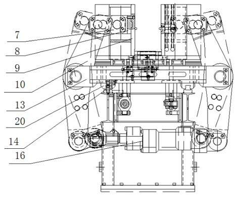
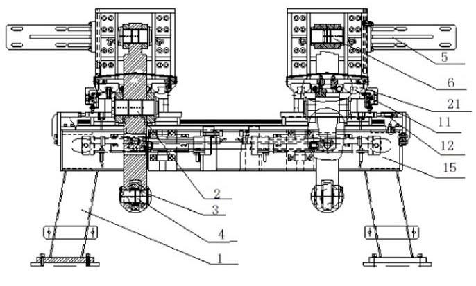
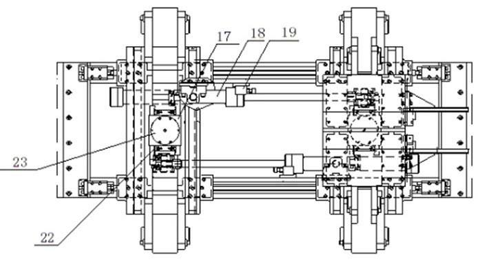
[0017] A clamping mechanism such as figure 1 , figure 2 , image 3 As shown, it includes a frame 1, on which an underframe 15 is installed, and the top of the underframe is provided with a two-column form-moving guide rail pair 14 horizontally, and each of the two ends of the form-moving guide rail pair is provided with a locking mold of the same structure. Device; the mold clamping device includes a crossbeam 13 perpendicular to the mold-moving guide rail, the bottom of the beam is provided with a mold-moving slider 20 to cooperate with the mold-moving guide rail, and the beam is provided with a two-column mold clamping perpendicular to the mold-moving guide rail The guide rail is 11, and the mold locking guide rail is provided with a pair of symmetrical hinge arm connecting seats 8, and the bottom of the hinge arm connecting seat is provided with a mold locking slid...


PUM


Abstract

The invention discloses a die locking mechanism, wherein, a die moving guide rail pair is utilized to lead two die locking device to move in the opposite directions; a die locking guide rail pair is utilized to close pivoted arm connecting seats; a die locking oil cylinder is taken as driving power and pivoted arms are used for transmission so as to achieve the closure or separation of the two pivoted arm connecting seats, and the two pivoted arm connecting seats can move synchronously with the help of a synchronous gear device; in addition, an anticollision rack and an anticollision block are additionally arranged on the die locking mechanism, so that the safety can be ensured when the die locking mechanism operates. Due to the effects of the mechanical principle and the guide rail pair,the die locking mechanism ensures that the stress central point is not changed when templates on the pivoted arm connecting seats act on a die, the templates are not easy to be deformed even if a large-scale die is closed, and the guide rail pair and a corresponding slide block are less vulnerable to abrasion; the pivoted arm-type closing is adopted, so that the closing force of the pivoted arm connecting seats can begreatly increased further, the die locking force is enough, the two pivoted arm connecting seats can move synchronously and can be closed synchronously with the help of the synchronous gear device at the same time, and the product quality can be enhanced greatly.

Description

technical field [0001] The invention relates to a mold clamping mechanism, in particular to a mold clamping mechanism which realizes mold clamping force in the form of a hinge arm. Background technique [0002] At present, the structural forms of the clamping units of large injection molding machines produced by injection molding machine manufacturers around the world can be roughly classified into three types: (1) mechanical clamping structure; (2) two-platen four-cylinder pressurized clamping Structure; (3) Two-plate single-cylinder direct pressure clamping structure. [0003] The three types of mold clamping structures have their own advantages and disadvantages, and a brief comparison is as follows: 1. The mechanical mold clamping mechanism is composed of a locking plate, a mold clamping hinge rod, and an oil cylinder drive device. The advantages: the mechanism operates reliably, and the movement speed Fast, low cost, simple hydraulic system, low energy consumption, etc...

Claims


Application Information

Patent Timeline
Patent Type & Authority Applications(China)
IPC IPC(8): B29C45/66
Inventor 谭炳立
Owner 开平雅琪塑胶机械模具厂
Why Eureka
Try Eureka