Guide mechanism of machine tool and machine tool

a technology of guide mechanism and machine tool, which is applied in the direction of manufacturing tools, mechanical devices, metal-working machine components, etc., can solve the problems of limited damping performance of hydrostatic pressure guide mechanism, significant reduction of slide resistance, and complicated arrangement of devices and pipes associated with the guide mechanism, so as to achieve high guiding accuracy and low friction. , the effect of high load capacity

Active Publication Date: 2016-04-28
TOSHIBA MASCH CO LTD
View PDF19 Cites 9 Cited by
  • Summary
  • Abstract
  • Description
  • Claims
  • Application Information

AI Technical Summary

Benefits of technology

[0086]As the guide mechanism for tilt prevention in this arrangement, the above-described arrangement of the guide mechanism simultaneously functioning as the hydrostatic guide mechanism and the sliding guide mechanism or an arrangement in which a part of the guide mechanism for tilt prevention is provided by the hydrostatic guide mechanism and the rest of the guide mechanism is provided by the sliding guide mechanism and the functions of the respective mechanisms are combined is provided. Accordingly, the guide mechanism supports the load and prevents the machine tool from tilting. In this arrangement, the guide mechanism for the machine tool having a high load capacity, a low friction, a high guiding accuracy and a high damping performance can be provided.
[0087]According to the guide mechanism for the machine tool and the machine tool in the aspect of the invention, the sliding guide mechanism and the hydrostatic guide mechanism can be simultaneously provided. A high load capacity and a low friction can be secured by the hydrostatic pressure guide mechanism and the guiding accuracy and the damping performance can be secured by the sliding guide mechanism. Consequently, the guide mechanism having a high load capacity, a low friction, a high guiding accuracy and a high damping performance and the machine tool having the guide mechanism can be provided.

Problems solved by technology

In other words, only the lubricating oil intervenes between the pair of slide surfaces, so that the pair of slide surfaces are in non-contact with each other, thereby significantly reducing the slide resistance.
However, since the hydrostatic pressure guide mechanism is configured to float an object using the oil film, a damping performance of the hydrostatic pressure guide mechanism is limitative.
Especially, a typical hydrostatic pressure guide mechanism using the lubricating oil cannot discharge the lubricating oil to the outside unlike an air static pressure bearing using air.
Accordingly, arrangements of devices and pipes associated with the guide mechanism are complicated.
However, in the sliding guide mechanism, since a load capacity is small and a friction coefficient is large, particularly, a friction coefficient is increased when the sliding guide mechanism is started and / or driven at a low speed, motion occasionally becomes unsmooth to affect a positioning accuracy.
However, even if a typical sliding guide mechanism is simply replaced by the hydrostatic pressure guide mechanism, a desired performance may fail to be obtained because of the above-described difference in characteristics.
Accordingly, when the sliding guide mechanism and the hydrostatic pressure guide mechanism are used in combination, the lubricating oil discharged to the outside is likely to be unrecovered and overflow.
The overflowing lubricating oil is likely to reach the sliding guide mechanism to adversely influence the sliding guide mechanism.

Method used


Image

  • Guide mechanism of machine tool and machine tool
  • Guide mechanism of machine tool and machine tool
  • Guide mechanism of machine tool and machine tool

Examples


first exemplary embodiment

Advantages of First Exemplary Embodiment

[0162]According to the first exemplary embodiment as described above, the following advantages can be obtained in addition to the respective advantages described in relation to the hydrostatic pressure guide mechanism 40 and the sliding guide mechanism 50.

[0163]In the first exemplary embodiment, the hydrostatic pressure guide mechanism 40 is a hermetically-closed hydrostatic pressure guide mechanism, in which the periphery is sealed by the seal portion 42 and the lubricating oil is supplied from the supply passage 43, recovered from the recovery passage 44, and is circulated into tank 61.

[0164]Accordingly, in the hydrostatic pressure guide mechanism 40, the lubricating oil can be prevented from overflowing to the outside through the periphery, or the overflowing of the lubricating oil can be restricted to the minimum level.

[0165]Further, even when the hydrostatic pressure guide mechanism 40 and the sliding guide mechanism 50 are provided toget...

second exemplary embodiment

[0170]FIGS. 7 to 8 show a second exemplary embodiment of the invention.

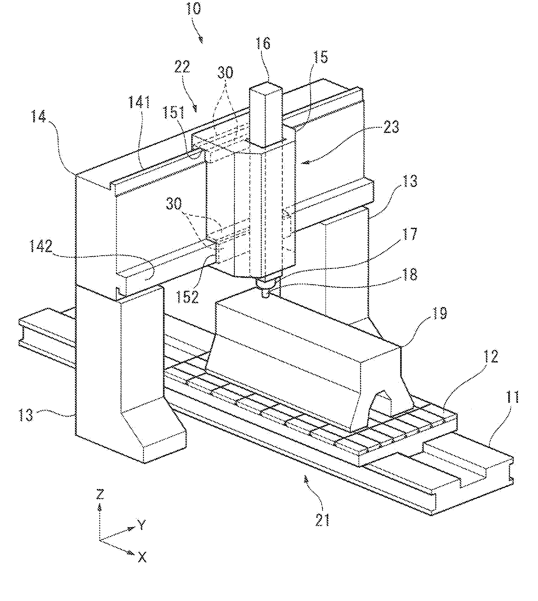
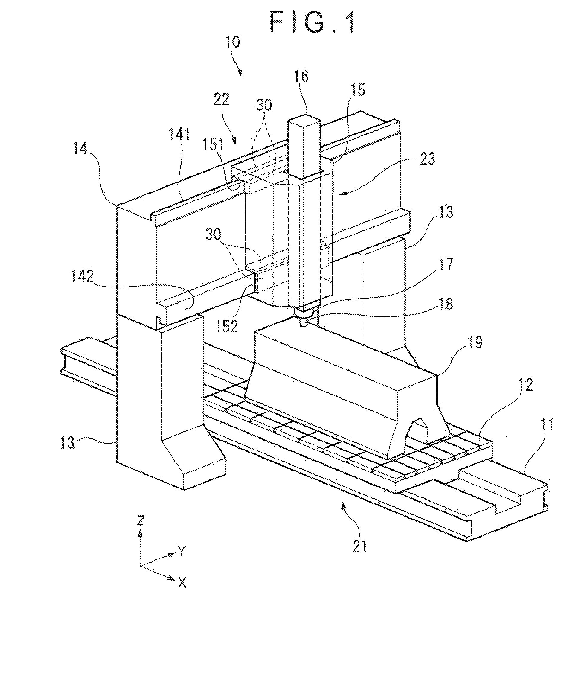
[0171]In the second exemplary embodiment, the guide mechanism 30 according to the second exemplary is provided to the machine tool 10 similar to that in the first exemplary embodiment.

In the second exemplary embodiment, the respective basic structures of the machine tool 10, the guide mechanism 30, the hydrostatic pressure guide mechanism 40 and the sliding guide mechanism 50 are the same. Hence, a duplicated description is omitted and a different structure(s) will be described below.

[0172]In the above first exemplary embodiment, the static pressure chamber 41 of the hydrostatic pressure guide mechanism 40 includes the annular groove 411, the inner part 412, the outer part 413 and the communication groove 414. Although the inner part 412 and the outer part 413 have the same depth, since the annular groove 411 and the communication groove 414 communicate with the seal groove 421, the inner part 412 functions as th...

third exemplary embodiment

[0180]FIGS. 9 to 10 show a third exemplary embodiment of the invention.

[0181]In the above first and second exemplary embodiments, the slide surface 51 and the smooth surface 49 are continuously formed on the surface at each end of the movement member 31. The hydrostatic pressure guide mechanism 40 is provided adjacent to the sliding guide mechanism 50.

[0182]In contrast, in the third exemplary embodiment, the hydrostatic pressure guide mechanism 40 and the sliding guide mechanism 50 are respectively formed in separate members.

[0183]As shown in FIGS. 9 and 10, in the third exemplary embodiment, the sliding guide mechanism 50 is formed in the movement member 31, but the hydrostatic pressure guide mechanism 40 is not formed therein.

[0184]However, on each end of the movement member 31, a block-shaped auxiliary movement member 48 is provided. The hydrostatic pressure guide mechanism 40 is formed in the auxiliary movement member 48.

[0185]The auxiliary movement member 48 is provided to an o...


PUM

PropertyMeasurementUnit
depthaaaaaaaaaa
pressureaaaaaaaaaa
static pressureaaaaaaaaaa

Abstract

A guide mechanism for a machine tool includes a movement member and a guide member in a form of first and second rails the movement member and the guide member relatively movable to each other. A hydrostatic pressure guide mechanism and a sliding guide mechanism are formed between the movement member and the first and second rails. The hydrostatic pressure guide mechanism includes a static pressure chamber, a seal portion sealing a periphery of the static pressure chamber, and a supply passage configured to supply a lubricating oil into the static pressure chamber.

Description

[0001]The entire disclosure of Japanese Patent Applications No. 2014-219652 filed Oct. 28, 2014 and No. 2015-088198 filed Apr. 23, 2015 is expressly incorporated by reference herein.TECHNICAL FIELD[0002]The present invention relates to a guide mechanism for a machine tool and a machine tool provided with the guide mechanism.BACKGROUND[0003]Typically, various movement mechanisms are used in the machine tool in order to move a workpiece (an object to be machined) and a tool for machining the workpiece to any relative positions.[0004]For instance, linear movement mechanisms are respectively provided in X axis, Y axis and Z axis to a support structure of a table on which the workpiece is placed or a support structure of a head to which the tool is attached in order to move the workpiece and / or the tool in three dimensions. Moreover, a rotary movement mechanism is used for changing a posture of the table and / or the head.[0005]Each of the movement mechanisms includes: two relatively movab...

Claims


Application Information

Patent Timeline
Patent Type & Authority Applications(United States)
IPC IPC(8): F16C29/02B23Q1/56B23Q1/38
CPCF16C29/025B23Q1/56B23Q1/38B23Q1/70F16C33/74F16C33/741F16C2322/39
Inventor TADA, ATSUSHISAGARA, MAKOTOTSUKIJI, TERUAKIARAI, TAKAOTAKEUCHI, KAZUHIROTSUNODA, SHUNINATSU, MASATOISHII, YUSUKETANAKA, YUYA
Owner TOSHIBA MASCH CO LTD
Why Eureka
Try Eureka