Mixer suspension

a technology of suspension and mixer, applied in the direction of mechanical equipment, vibration suppression adjustment, transportation and packaging, etc., can solve the problems of only achieving balance, unsatisfactory walking, and subject to a certain amount of imbalance, and achieve the effect of enhancing the ability of the spring mounting bushing

Active Publication Date: 2006-01-05
RED DEVIL EQUIP
View PDF24 Cites 31 Cited by
  • Summary
  • Abstract
  • Description
  • Claims
  • Application Information

AI Technical Summary

Benefits of technology

[0009] In a further aspect, the present invention includes an improved spring mounting bushing arrangement having a bushing with a V-groove accepting an end turn of a helically wound tension spring, with an included angle of the V-groove allowing a relatively loose fit of the end turn in the V-groove. Providing such a loose fit enhances the ability of the spring mounting bushing to react to and recover from misalignment of the spring end turn and the bushing, returning the end turn into proper alignment after the end turn is dislodged from the bushing as a result of a shock load. In one embodiment the bushing is free to rotate, and in another embodiment, the bushing is fixed against rotation. In a further aspect, the fixed bushing may include an eccentric adjustment feature to allow selection from among a plurality of mounting lengths for the springs of the present suspension. In a still further aspect, the present invention provides the convenience of a degree of self-leveling of the mixing frame assembly when it is at rest.

Problems solved by technology

While such vortex mixers have enjoyed a degree of popularity, they have also been subject to a certain amount of imbalance, caused by a range of density and viscosity in the materials (typically liquids) being mixed.
However, such balance was only achieved with one volume, density and viscosity of material to be mixed.
Such walking is undesirable, particularly when the mixer is located on a surface elevated above a floor, as for example, when the mixer is “stacked” on top of other equipment as is sometimes done in paint mixing facilities.

Method used


Image

  • Mixer suspension
  • Mixer suspension
  • Mixer suspension

Examples


embodiment 10

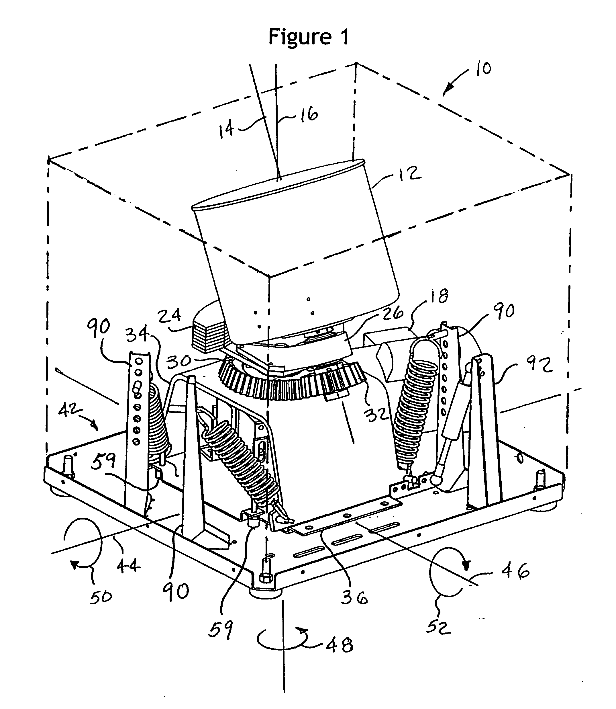
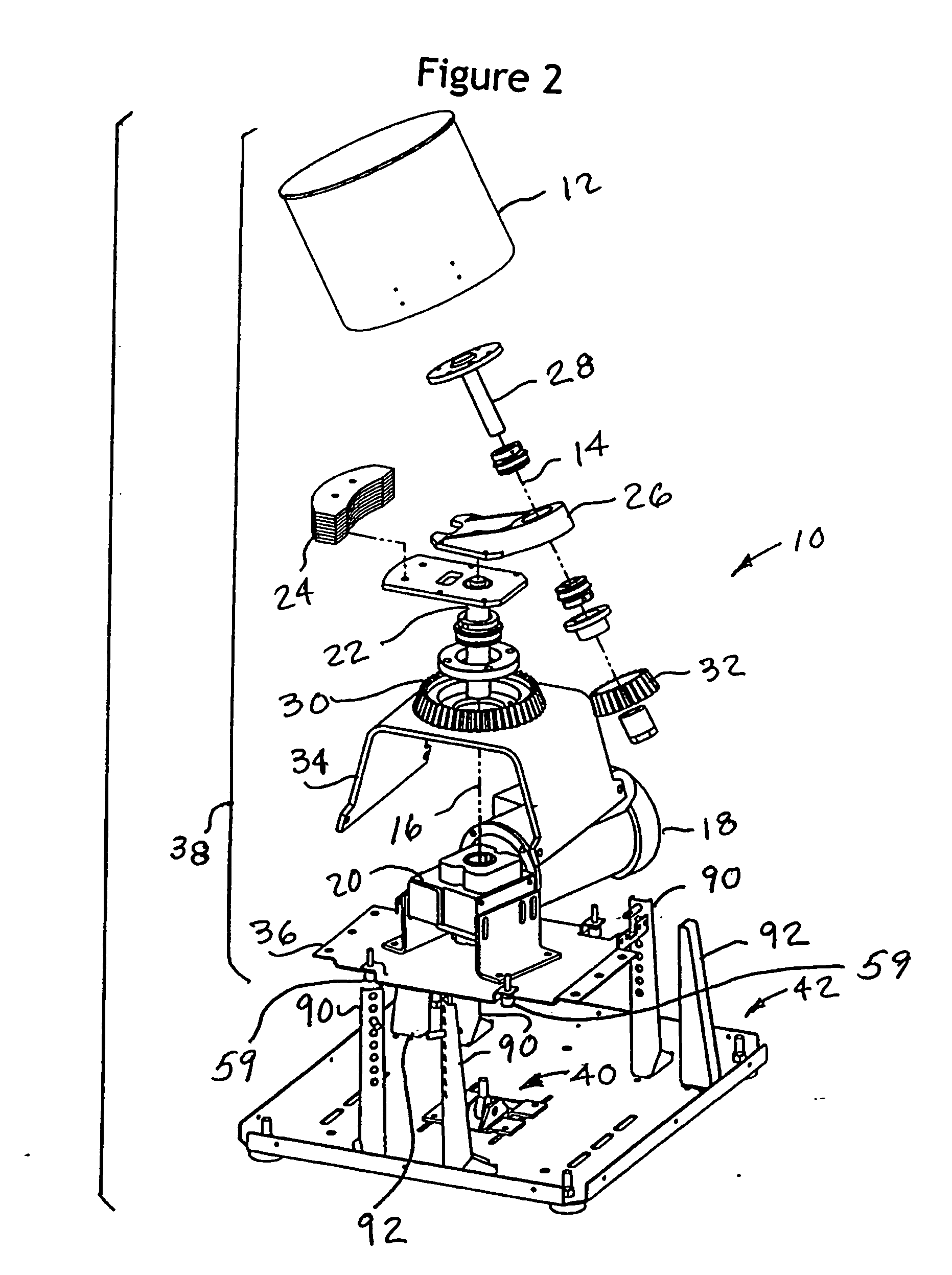
[0093] Referring now to FIG. 2A, an exploded view of an alternative embodiment 10′ of the mixer 10 shown in FIGS. 1 and 2 may be seen. This embodiment has the same electric motor 18 operating through the right angle gear reducer 20 to rotate the orbit shaft 22 carrying a counterweight 24′ and the rotating arm 26 on which a holder 12′ is mounted using the spin shaft 28 supported for rotation about the stationary bevel ring gear 30 via the pinion gear 32. Holder 12′ may be the same as holder 12, if desired. The embodiment 10′ of FIG. 2A differs from that shown in FIG. 2 in that the top mix frame element 34 has been replaced by a gear support plate 34′ mounted to the pair of brackets 35 for gear reducer 20. In this embodiment, gear 30 is mounted to gear support plate 34.′ The brackets 35 are fastened to a modified bottom mix frame member 36.′ The components of the holder 12′ through the bottom mix frame member 36′ make up a modified mixing frame assembly or paint container holder assem...

embodiment 40

[0118] Referring now to FIGS. 13, 14, and 15, an alternative embodiment 40′ for the pivoting support 40 may be seen. This embodiment of a pivoting support 40′ may utilize an isolator 146 which is commercially available. In this embodiment, the elastomeric shock mount isolator 146 has a steel mounting plate 148 embedded within an elastomeric body 150, made of, for example, synthetic or natural rubber. Preferably a rigid tube 152, which may also be made of steel, is molded in body 150. In use, one of the plate and tube 148, 152 is secured to the base 42 and the other of the plate and tube 148, 152 is secured to the mixing frame assembly 38, preferably at the bottom mix frame weldment 36.

[0119] As mentioned above, it is within the practice of the present invention to have a pivoting support which does not permit yaw motion. Furthermore, it is also within the scope of the present invention to have a pivoting support which has offset pivot points or locations for the respective rotationa...

embodiment 210

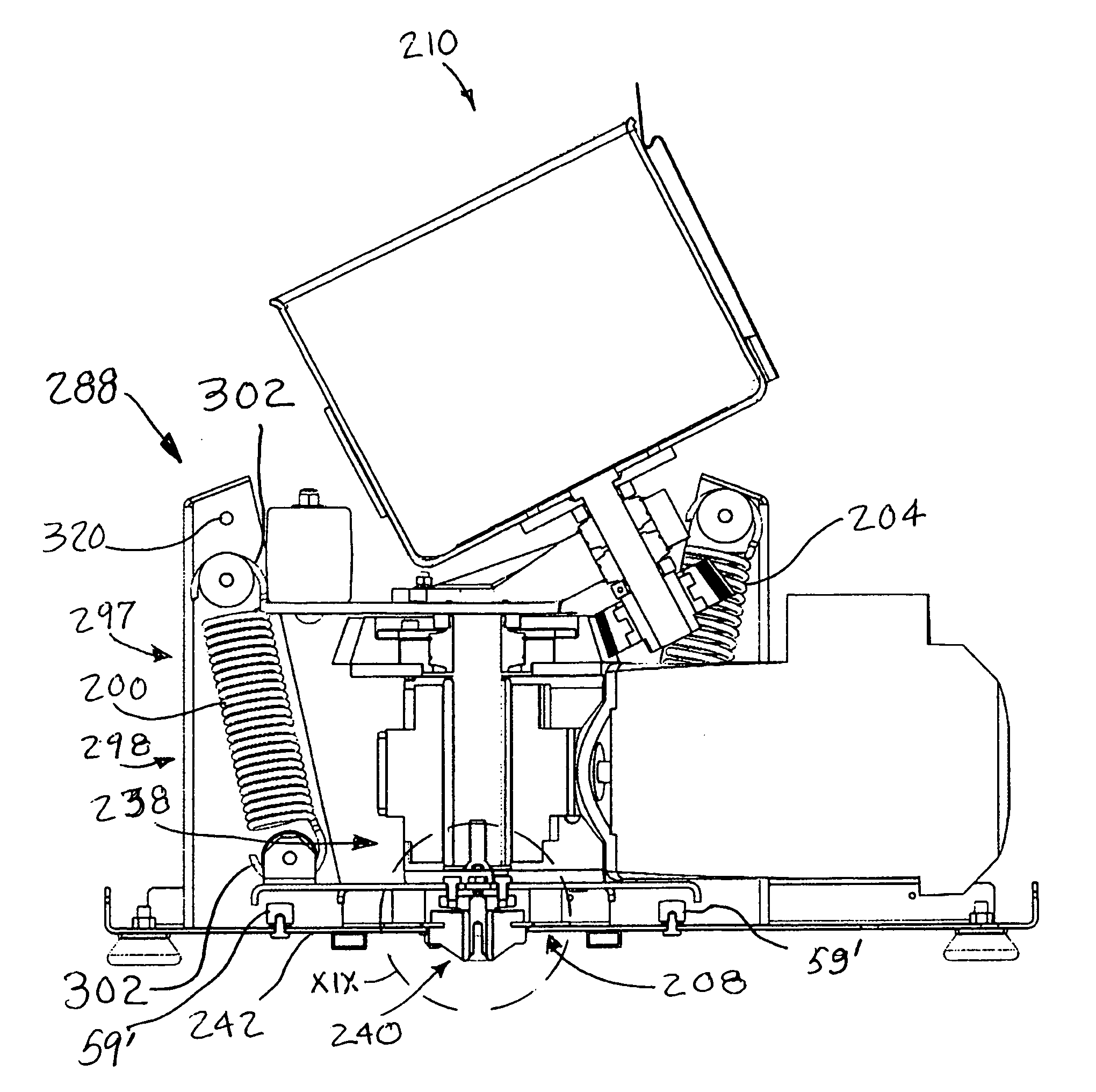
[0121] Referring now to FIGS. 17-40, and most particularly to FIGS. 17-22, an alternative embodiment 210 of the mixer 10 may be seen. Like mixer 10, mixer 210 has a suspension system 288 utilizing a pivoting support 240 and a plurality of springs 298, and generally operates in the same way and according to generally the same principles as described for mixer 10. Mixer 210 has a damper 208 preferably in the form of an annular member or ring 212 formed of commercially available viscoelastic polymer material. In the practice of the present invention, it has been found desirable to use a ring having a 70 durometer (shore 00) but it is to be understood that other geometries and durometers may be used in the practice of the present invention for damper element 208. Furthermore, various shapes for one or more dampers or damper elements may be used, although, as is illustrated in FIGS. 21 and 22, a ring having dimensions of 1.00 inches thickness, 5.00 inches OD, and 2.81 inches ID has been ...


PUM


Abstract

An improved suspension apparatus and method for damping vibration arising in liquid vortex mixers of the type pivotably supporting a mixing frame assembly and suspending the assembly by at least one spring for mixing a liquid coating using both spin and orbital rotational movements. A pivoting support is located between the mixing frame assembly and a base. A damper in the form of an annular ring is used to damp pivoting movement of the mixing frame assembly. Various pivoting mounts may be used to pivotably support the mixing frame on a base. A bushing provides accommodation of a misaligned spring mounting end turn using a V-groove to retain the spring mounting end turn, and may include an eccentric feature to allow adjustment of the spring mounting length.

Description

CROSS REFERENCE TO RELATED APPLICATION [0001] This application is a Continuation-In-Part of U.S. application Ser. No. 10 / 891,446, filed Jun. 30, 2004, the entire contents of which are hereby expressly incorporated by reference.BACKGROUND OF THE INVENTION [0002] In the past, vortex mixers have been used to mix pigment and vehicle in liquids such as paint, typically in 5 gallon cylindrical containers. Such vortex mixers achieved mixing by spinning the container on its cylindrical axis, while that axis was positioned at an angle to a central orbit axis about which the container was simultaneously orbited as well as spun. While such vortex mixers have enjoyed a degree of popularity, they have also been subject to a certain amount of imbalance, caused by a range of density and viscosity in the materials (typically liquids) being mixed. While a vortex was created in the material being mixed, the vortex assumed different shapes and positions within the container, depending upon the density...

Claims


Application Information

Patent Timeline
Patent Type & Authority Applications(United States)
IPC IPC(8): B01F11/00
CPCB01F9/0001B01F15/0074B01F2215/005F16F15/08F16F1/3732F16F15/022F16F15/067F16F1/126B01F29/10B01F35/421B01F2101/30
Inventor SCHULZ, DANIELROHOSY, OSZKARCURTIS, AARON
Owner RED DEVIL EQUIP
Why Eureka
Try Eureka