Pressure limiting valve

a technology of pressure limit valve and pressure limit, which is applied in the direction of safety valves, check valves, functional valve types, etc., can solve the problems of affecting the balance of pressure medium volume, prone to vibration, and considerable acoustic load, and achieve enhanced damage effect

Inactive Publication Date: 2007-06-12
BOSCH REXROTH AG
View PDF16 Cites 30 Cited by
  • Summary
  • Abstract
  • Description
  • Claims
  • Application Information

AI Technical Summary

Benefits of technology

[0008]In contrast, the invention is based on the object of furnishing a pressure limiting valve in which the damping effect is enhanced.

Problems solved by technology

It is one drawback of these pressure limiting valves, however, that they are very prone to vibration due to their opening dynamics in the event of pressure fluctuations.
The valve bodies, which vibrate owing to hydraulic excitation, may result in a considerable acoustic load, and in unfavorable cases in the destruction of an associated valve seat or of the spring acting in the closing direction.
This pressure medium volume balance is impaired by the throttle effect in the damping gap, with kinetic energy of the valve body and of the damping piston being converted into heat, and the axial translation of the valve body thus being decelerated and damped.
It is a drawback in this known solution that the axial structural space of the pressure limiting valve is increased by the damping chamber connected on the pressure port side and having the damping piston arranged in it.
Moreover a comparative technological complexity is necessary in the manufacture, for the pressure port has to be formed by oblique bores that are difficult to produce.
It is a drawback in this return-side low-pressure damping that 100% filling of the damping chamber with pressure medium must always be ensured.
This filling may only be carried out with comparative complexity during installation of the valve.
This risk is particularly high if the return line is capable of being emptied entirely, or if air dissolved in the pressure medium bubbles out in the transition from high pressure to low pressure.

Method used


Image

  • Pressure limiting valve
  • Pressure limiting valve

Examples


Embodiment Construction

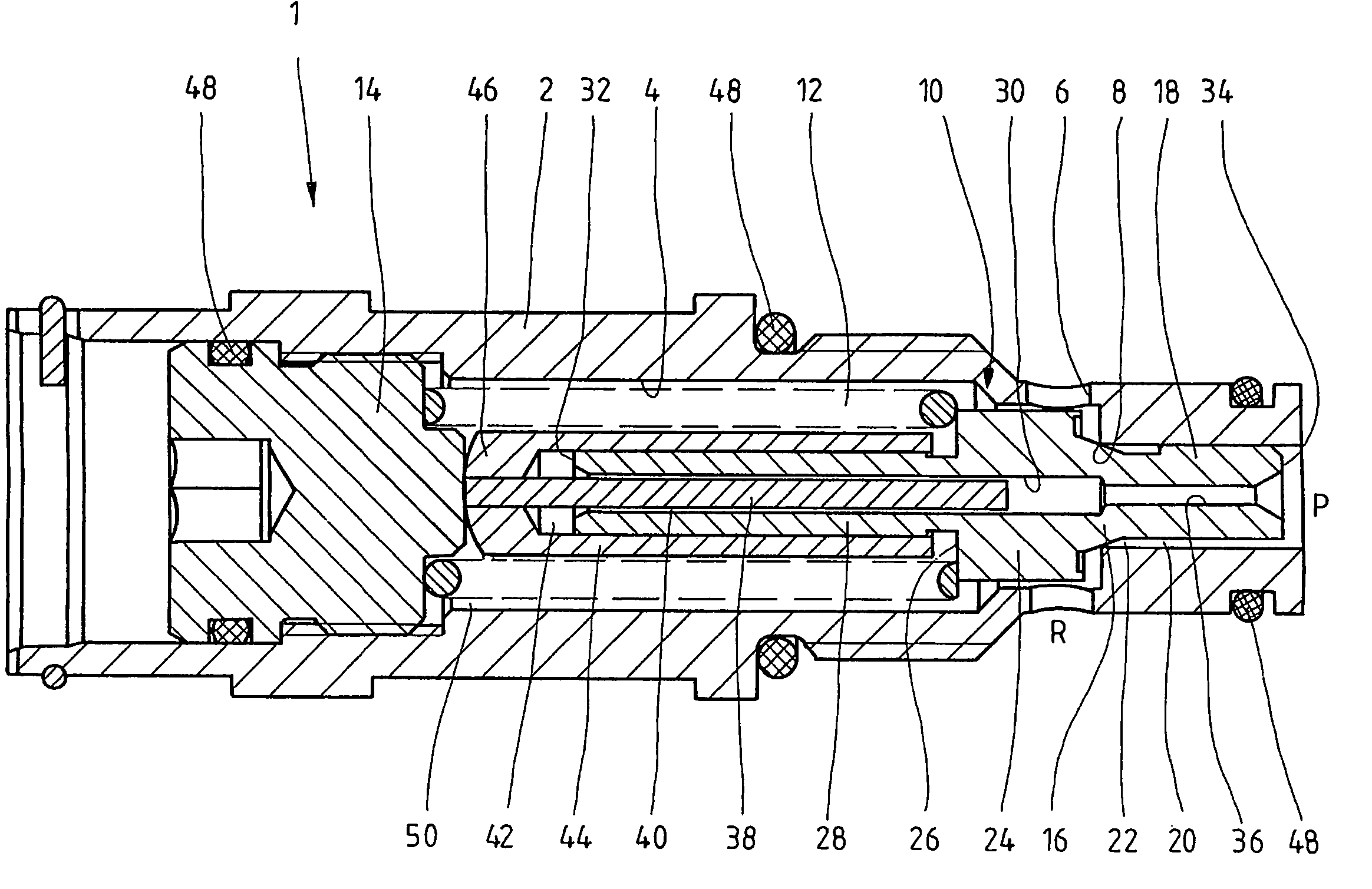
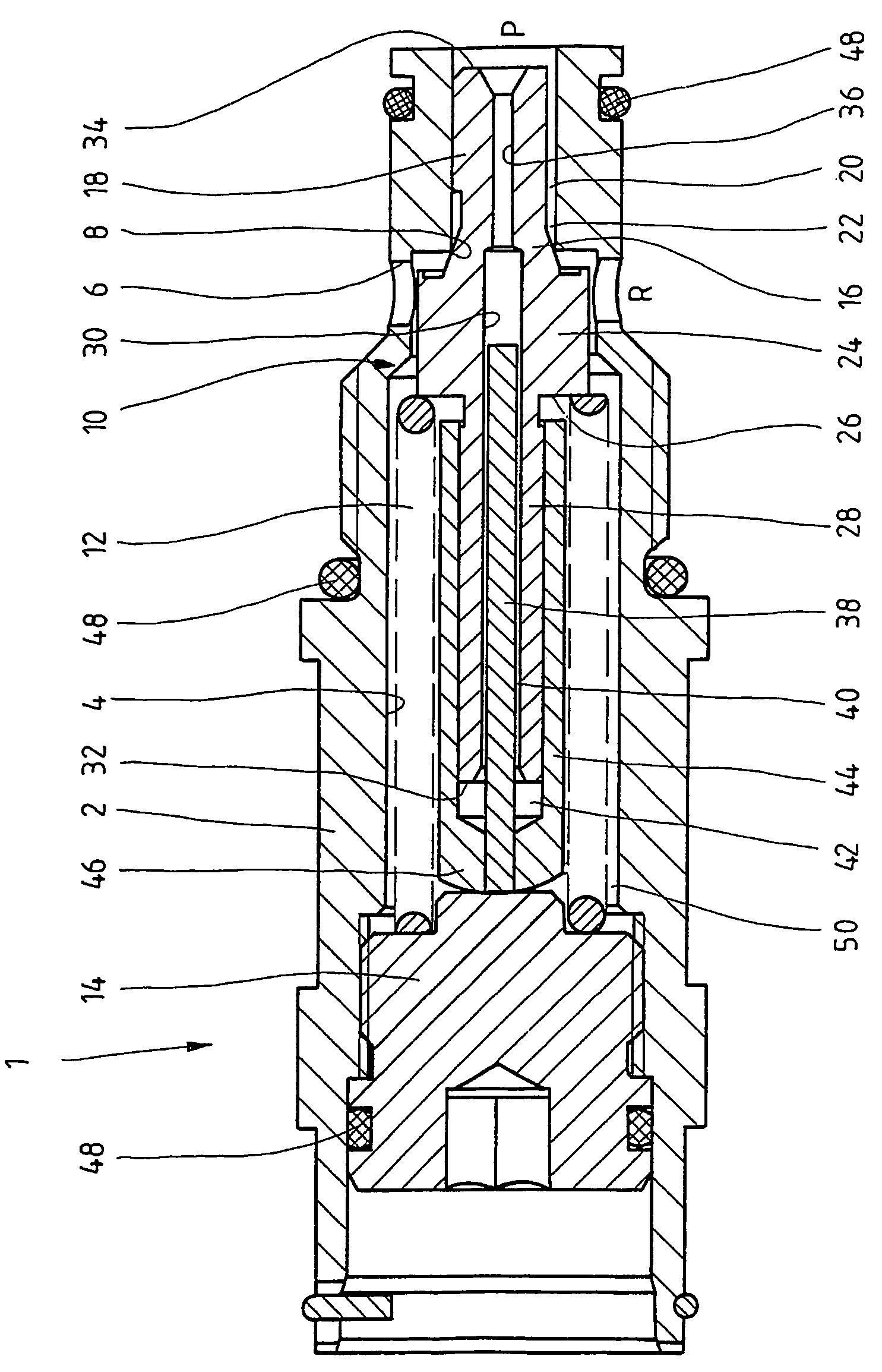
[0023]The pressure limiting valve 1 comprises a bush 2, the valve bore 4 of which is stepped back from left to right in the representation. The right-hand end-side opening of the valve bore 4 forms a pressure port P, whereas a return port R is formed by a configuration of radially arranged bores 6 radially opening into the valve bore 4.

[0024]In the range between the return port R and the pressure port P, a radial step of the valve bore 4 forms a valve seat 8 against which a valve body 10 is biased through the intermediary of a closing spring 12.

[0025]The left-hand end portion of the valve bore 4 in the representation of the FIGURE is closed by a set screw 14 screwed into a radially expanded portion of the valve bore 4. The closing spring 12 is supported on the set screw 14, so that the bias of the closing spring 12 and thus the adjustable maximum system pressure is variable by modifying the screw-in depth.

[0026]The represented valve body 10 has a valve cone 16 which is seated on the...


PUM


Abstract

What is disclosed is a a pressure limiting valve comprising a valve body, the axial movement of which is damped by means of a damping device. In accordance with the invention, the damping device includes a damping chamber formed on the return side, that is subjected to the system pressure acting on a pressure port.

Description

INTRODUCTION[0001]The invention relates to a pressure limiting valve in accordance with the preamble of claim 1.BACKGROUND[0002]Pressure limiting valves serve to limit a system pressure. They may have the form of directly controlled seat valves. Other designs are spool valves or disk valves. These, too, may fundamentally be vibrationally damped by the kind of damping presently applied, if they are controlled directly. Furthermore the piloted design is also possible. When a pre-set maximum pressure is exceeded, a connection from a pressure port to a return port is opened via the pressure limiting valve. In the most simple case the pressure limiting valves are controlled directly and thus have a simple construction and may be manufactured at low cost. Such directly controlled pressure limiting valves have high opening dynamics, so that pressure peaks in the system may be reduced very rapidly. It is one drawback of these pressure limiting valves, however, that they are very prone to vi...

Claims


Application Information

Patent Timeline
Patent Type & Authority Patents(United States)
IPC IPC(8): F16K17/04F16K21/10
CPCF16K17/0433Y10T137/785Y10T137/7929Y10T137/7851F16K17/04F16K15/063
Inventor WILHELM, MICHAEL
Owner BOSCH REXROTH AG
Why Eureka
Try Eureka