Antivibration device

a technology of antivibration and vibration, which is applied in the direction of shock absorbers, machines/engines, manufacturing tools, etc., can solve the problems of difficult adaptation of the resonance frequency to the operating frequency range of the work apparatus, premature tiring of the operator, and disadvantageous non-linear material characteristics of the rubber, etc., to achieve low tension level, low space requirement, and small but effective antivibration elements

Inactive Publication Date: 2006-02-07
ANDREAS STIHL AG & CO KG
View PDF6 Cites 31 Cited by
  • Summary
  • Abstract
  • Description
  • Claims
  • Application Information

AI Technical Summary

Benefits of technology

[0037]In a practical embodiment of the above-mentioned variation, the metal spring is configured as a helical spring having a longitudinal axis. The vibration damper is arranged at least approximately coaxially to the helical spring. This results in a compact, space-saving configuration. The coaxial configuration avoids asymmetries in the introduction of force. The helical spring and the vibration damper are essentially loaded free of tilting. There results a low tension level as a consequence of which an overall small but effective antivibration element can be built up.
[0038]At least at one of its ends, the helical spring is held on a threaded lug which accommodates turns of the spring. This results in a reliable force introduction in all spatial axial directions. In addition to pressure forces, tension forces can also be introduced. The assembly can take place in a simple manner via a simple threadable engagement of the helical spring on the threaded lug.
[0039]In a practical embodiment, the metal spring is mounted at one end of the handle unit and the vibration damper is mounted on the opposite-lying end of the handle unit. There results an elastic parallel connection of both components with an overall low requirement of space. The mutually opposite arrangement of the two components leads to the situation that the motor housing extends laterally over the handle unit in the corresponding region and so leads to a protecting covering. In combination with the coaxial configuration, the helical spring and the damping element form a continuous unit having a force introduction into the handle unit at both ends

Problems solved by technology

The oscillations generated thereby in the handle can lead to a premature tiring of the operator.
The essentially non-linear material characteristics of the rubber can be disadvantageous in this context.
An adaptation of the resonance frequency to the operating frequency range of the work apparatus is therefore difficult.
An operation of an antivibration element of this kind in a quasi-linear range is only possible for a correspondingly large configuration of the antivibration element for which sufficient mounting space is not always available.
Blocking the transverse expansion leads, with rubber, to a considerable stiffening, which makes an adaptation to the excitation frequencies to be dampened difficult.
A further disadvantage of rubber as a material for a damping element lies in its frequency-dependent stiffness.
For an adequate vibration decoupling at high excitation frequencies, a very soft dimensioning of the antivibration element is required, which, under some circumstances, c

Method used


Image

  • Antivibration device
  • Antivibration device
  • Antivibration device

Examples


Embodiment Construction

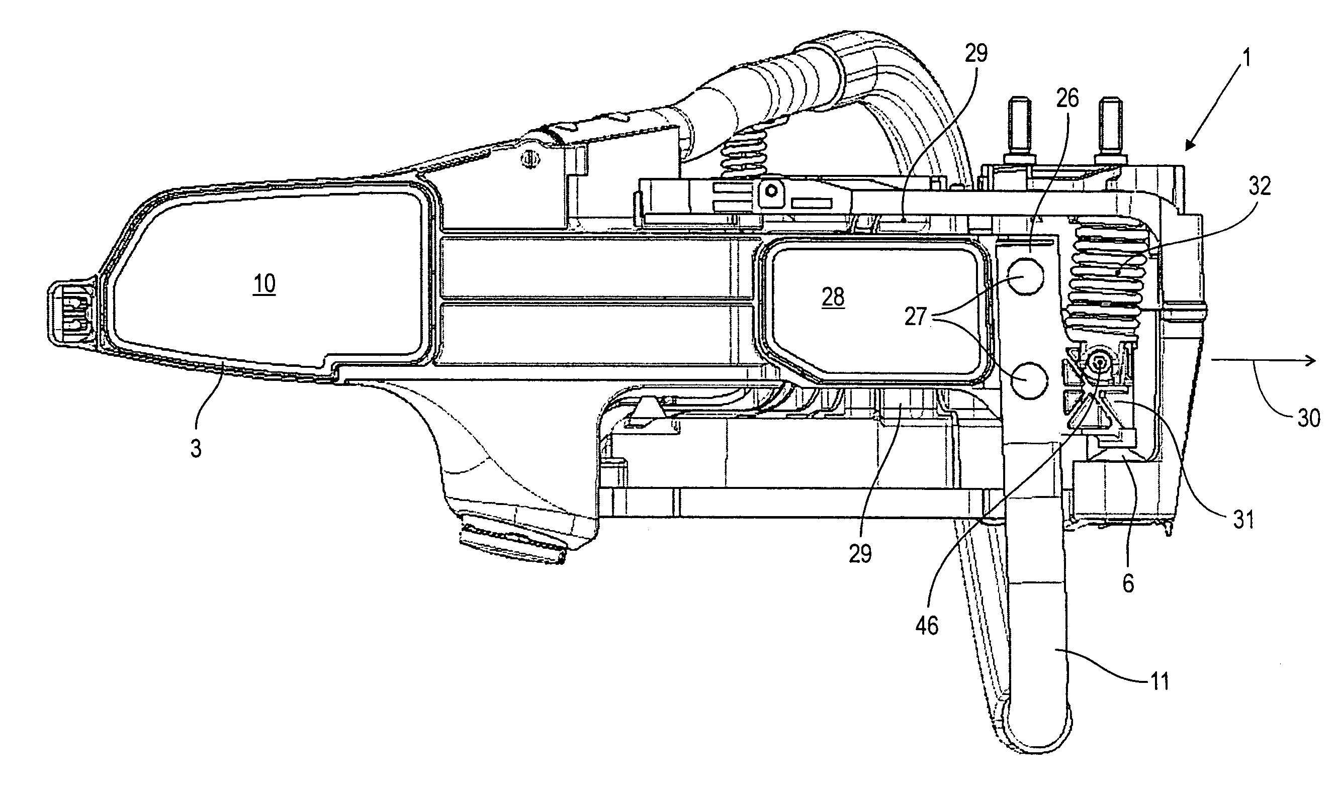
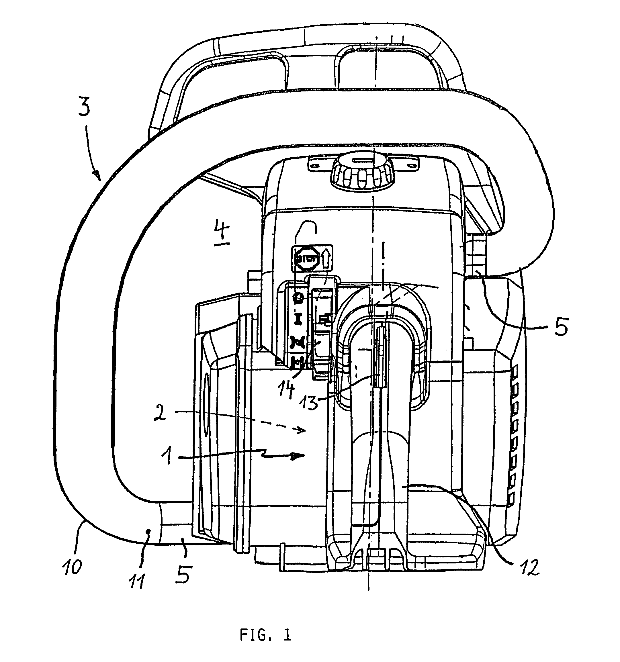
[0055]FIG. 1 shows a rearward view of a portable handheld work apparatus 4, such as a motor-driven chain saw. The work apparatus 4 can also be a cutoff machine, a suction / blower apparatus, a brushcutter or the like. The work apparatus 4 includes a motor unit 1 having an internal combustion engine 2. A rearward handle 12 is mounted on the motor unit 1 and includes a lock lever 13 for a throttle lever (not shown) as well as an actuating lever 14 for an automatic stop of the engine 2. A handle unit 10 in the form of a tubular handle 11 is fixed to the motor unit 1 with two antivibration elements 5. The tubular handle 11 thereby defines a vibration-insulated unit 3. A common configuration of a tubular handle 11 and of the handle 12 as a vibration-insulated handle unit 10 can also be practical. A further possibility comprises fixing the engine 2 in the apparatus housing via antivibration elements 5 whereby the apparatus housing together with the handle unit 10 becomes a vibration-insulat...


PUM

PropertyMeasurementUnit
Fractionaaaaaaaaaa
Fractionaaaaaaaaaa
Pore sizeaaaaaaaaaa

Abstract

An antivibration device is mounted between a motor unit (1) having an internal combustion engine (2) and a vibration-insulated unit (3) of a portable handheld work apparatus (4) such as a motor-driven chain saw, cutoff machine, suction/blower apparatus or the like. The antivibration device (5) includes a vibration damper (6) made of foamed elastic material (7).

Description

RELATED APPLICATION[0001]This is a continuation-in-part application of U.S. patent application Ser. No. 10 / 133,586, filed Apr. 29, 2002, now abandoned and claims priority of German patent application 101 21 029.9, filed Apr. 28, 2001, the entire content of which is incorporated herein by reference.BACKGROUND OF THE INVENTION[0002]The internal combustion engine of a portable handheld work apparatus such as a motor-driven chain saw, a cutoff machine, suction / blower apparatus or the like generates oscillations in its rpm range. These oscillations are, for example, noticeable as vibrations in a handle for guiding the work apparatus. A further component of the oscillatory excitation is regularly generated by the tool which is driven by the engine. The tool can, for example, be a saw chain, a cutoff disc, a cutting knife or the like. The oscillations generated thereby in the handle can lead to a premature tiring of the operator.[0003]The motor unit of a portable handheld work apparatus an...

Claims


Application Information

Patent Timeline
IPC IPC(8): F02B75/06F02B63/02F16F1/37F16F15/08
CPCF02B63/02F16F15/08F16F1/37F02B2063/046
Inventor MENZEL, JOHANNESKELLER, MARKUSLUX, HELMUTVON HILLER, CHRISTOPHWOLF, GUNTERGUIP, ANDREAS
Owner ANDREAS STIHL AG & CO KG
Why Eureka
Try Eureka