Chain tensioner

a chain tensioner and tensioner technology, applied in the direction of belts/chains/gearrings, mechanical equipment, etc., can solve the problems of inability to adjust the damping properties of tensioners individually, and inability to adjust the damping properties of tensioners. , to achieve the effect of accurate damping adjustment, small size and increased actuator siz

Inactive Publication Date: 2011-10-20
TSUBAKIMOTO CHAIN CO
View PDF12 Cites 30 Cited by
  • Summary
  • Abstract
  • Description
  • Claims
  • Application Information

AI Technical Summary

Benefits of technology

The actuator can be operated by means of a piezoelectric element, and in this case, more accurate adjustment of damping can be achieved and operational failures due to vibration, engine heat, and similar causes are less likely to

Problems solved by technology

However, the effectiveness of the damping action is highly dependent, not only on the engine, but on changes in the operating conditions of a given engine.
Hence it is difficult to make different adjustments for optimum damping of tensioners individually.
Although it is possible to control damping by providing a V-shaped groove 523 on the side the plunger 520 as shown in FIG. 6, and to control damping property by varying the width and depth of the groove, it is necessary to determine the appropriate groove dimensions for each engine in which the tensioner

Method used


Image

  • Chain tensioner
  • Chain tensioner
  • Chain tensioner

Examples


Embodiment Construction

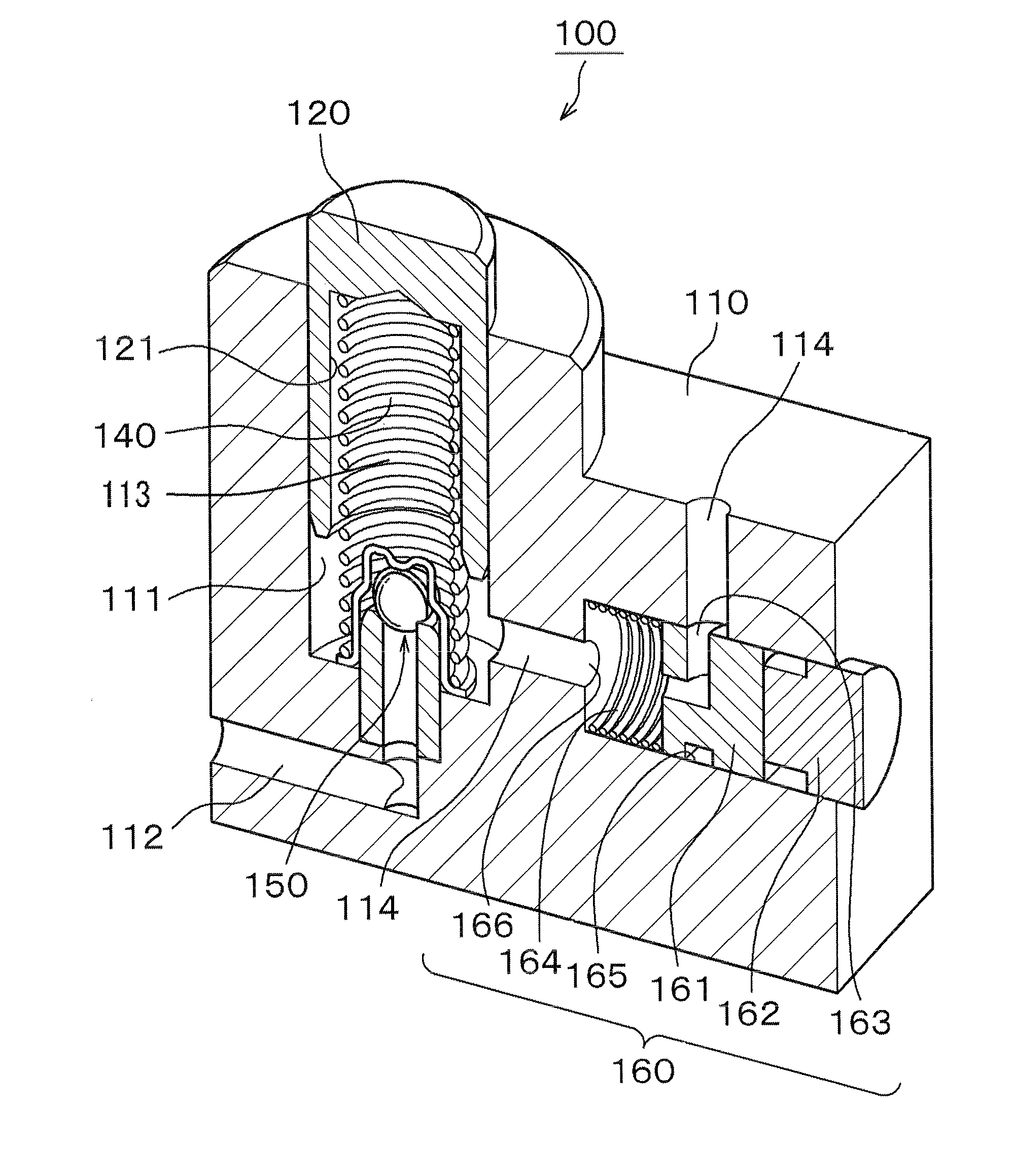
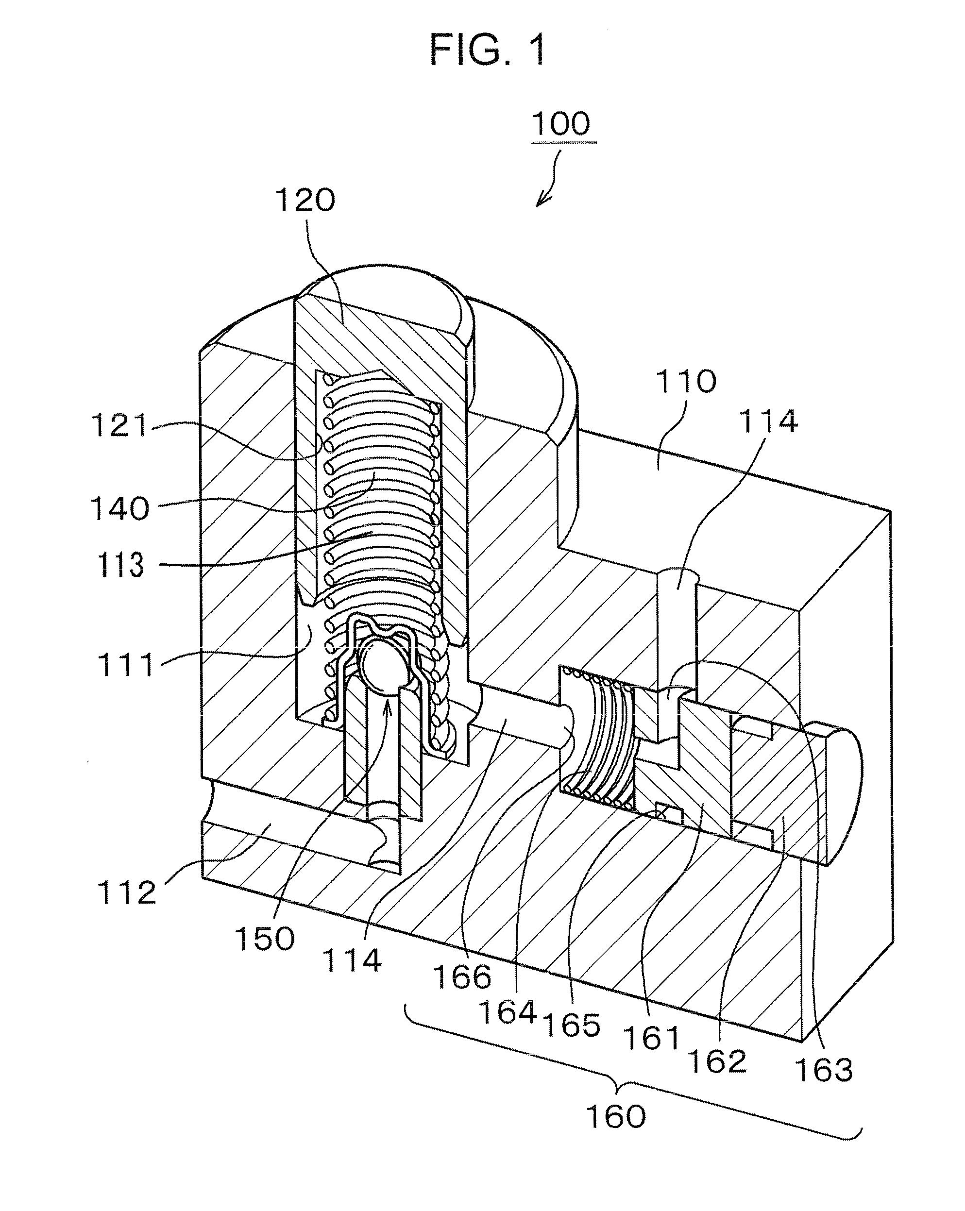
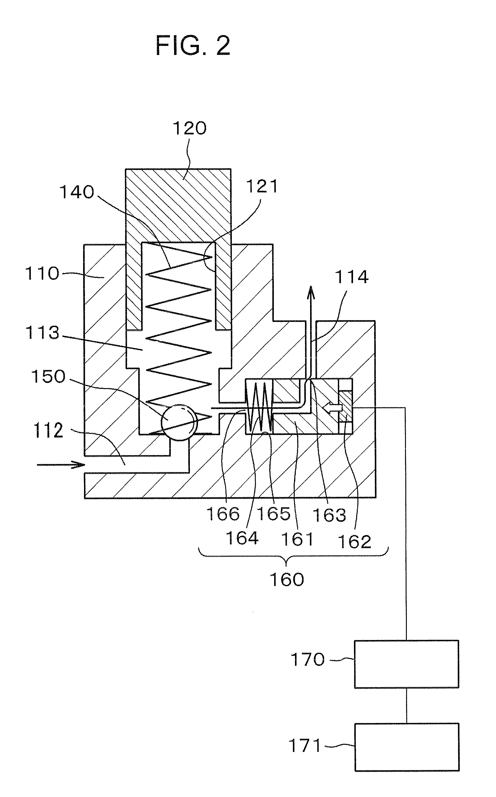
As shown in FIGS. 1 and 2, a chain tensioner 100 comprises a housing 110 having a cylindrical plunger-accommodating hole 111 having an end opening in a wall of the housing. A plunger 120, at least part of the outer peripheral surface of which is cylindrical, is slidable in the plunger-accommodating hole 111 and protrudes therefrom through the end opening. A plunger-biasing coil spring 140, partly within a spring-receiving hole 121 inside the plunger, is in compression between and end of hole 121 adjacent the protruding end of the plunger, and the bottom of the plunger-accommodating hole 111.

The housing 110 is provided with an oil inflow channel 112 for supplying oil under high pressure to a high pressure oil chamber 113 formed by the plunger 120 and the plunger-accommodating hole 111. A check valve 150 prevents the oil from flowing from the plunger-accommodating hole through the oil inflow channel 112.

The housing is also provided with an oil outflow channel 114 for discharging oil f...


PUM


Abstract

In a hydraulic tensioner, a tensioner housing is provided with an oil outflow channel communicating with a high pressure oil chamber formed by a plunger and the tensioner housing. A control valve in the oil outflow channel can be adjusted manually or automatically to optimize the damping performance of the tensioner in different engines and under different operating conditions, thereby obviating individualized machining of tensioner components to achieve optimum damping.

Description

CROSS REFERENCE TO RELATED APPLICATIONSThis application claims priority on the basis of Japanese Patent Application 2010-095730, filed on Apr. 19, 2010. The disclosure of Japanese Patent Application 2010-095730 is incorporated by reference.FIELD OF THE INVENTIONThe invention relates to a chain tensioner, comprising a tensioner housing in which a cylindrical plunger-accommodating hole is formed, and a cylindrical plunger, slidable in the plunger-accommodating hole and protruding therefrom through an opening in a wall of the housing. In a chain tensioner, the plunger and the plunger-accommodating hole cooperatively form a high pressure oil chamber, and the plunger is biased in the protruding direction in order to maintain adequate tension in a transmission chain such as the timing chain of an internal combustion engine.BACKGROUND OF THE INVENTIONIn a typical application of a chain tensioner, a transmission chain is engaged with, and driven by, an engine crankshaft sprocket, and is in ...

Claims


Application Information

Patent Timeline
IPC IPC(8): F16H7/08
CPCF16H7/0836F16H2007/0859F16H2007/0812F16H2007/0806
Inventor NAKANO, YOSHIKAZUKUNIMATSU, KOHEI
Owner TSUBAKIMOTO CHAIN CO
Why Eureka
Try Eureka