Reverse circulation drill and gripper for same

A reverse circulation and gripper technology, applied in drill pipes, drill pipes, drilling equipment, etc., can solve the problems of unstable drilling rigs, increase the load of drilling rigs, and bending of drill pipes, so as to improve safety performance and service life. , Improve the drilling quality and avoid the effect of overturning

Inactive Publication Date: 2011-07-06
BEIJING SANY HEAVY MASCH CO LTD
View PDF4 Cites 9 Cited by
  • Summary
  • Abstract
  • Description
  • Claims
  • Application Information

AI Technical Summary

Problems solved by technology

During the construction process, the reverse circulation drilling rig is generally directly supported on the ground or the platform through its base, and during the drilling process, the drill pipe generates a large vibration, due to the reaction force of the drill pipe on the reverse circulation drilling rig, the reverse circulation The drilling rig is easy to move on the ground or on the platform, which affects the drilling quality of the reverse circulation drilling rig. When the movement is large or violent, it may even cause the bending of the drill pipe and affect the service life of the drill pipe; When drilling inclined holes, the reverse circulation drilling machine needs to be tilted. The reaction force during the drilling operation may cause the drilling machine to be unstable or even overturned, causing injury to the site personnel and damage to the drilling machine and other engineering equipment.
[0004] In order to solve the above problems and reduce the movement of the drilling rig on the ground or on the working platform when drilling, it is usually adopted to increase the weight of the drilling rig base or increase the counterweight for the drilling rig. However, due to the large reaction force received by the drilling rig during work, By increasing the weight of the base and increasing the counterweight, not only the load of the drilling rig body is increased, but the effect of reducing the movement of the drilling rig is not obvious

Method used


Image

  • Reverse circulation drill and gripper for same
  • Reverse circulation drill and gripper for same
  • Reverse circulation drill and gripper for same

Examples


Embodiment Construction

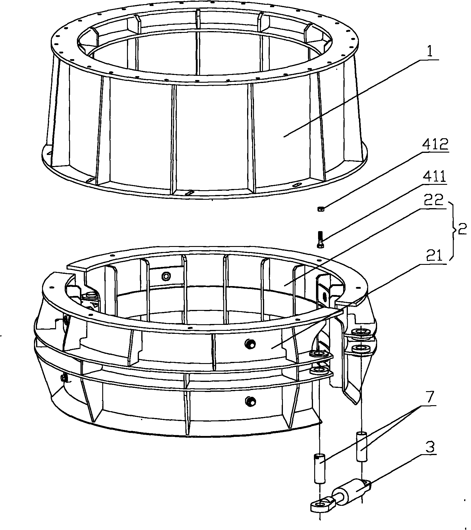
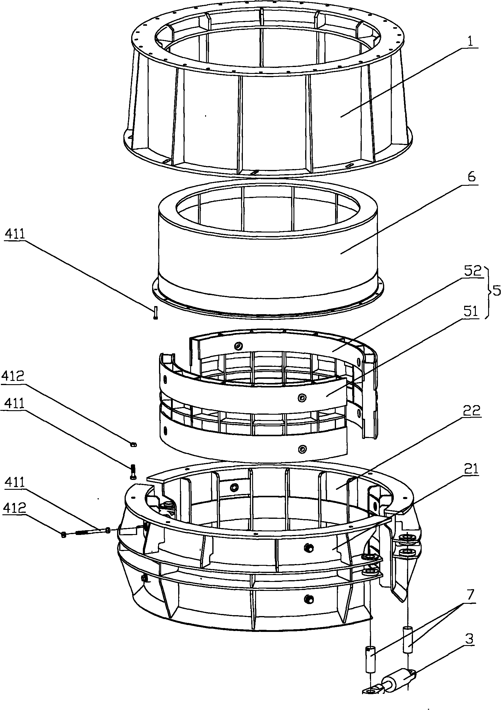
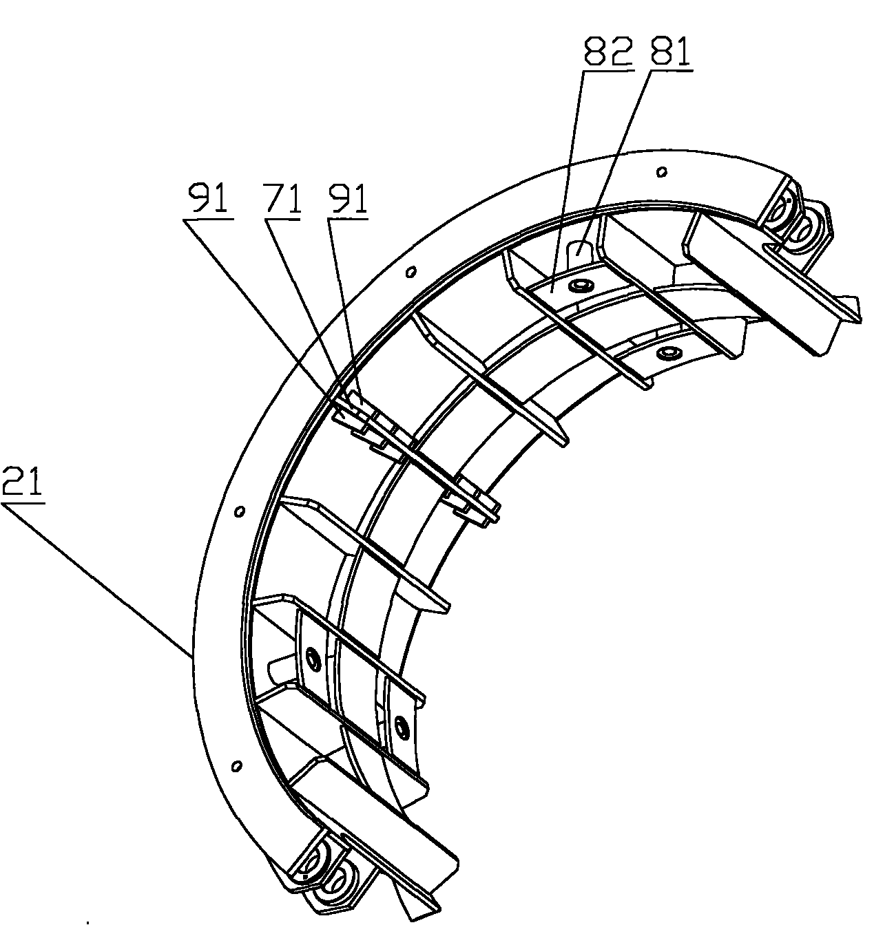
[0026] The core of the present invention is to provide a clamper for a reverse circulation drilling machine, which can effectively reduce the movement of the reverse circulation drilling machine during the drilling process; another core of the present invention is to provide a clamper including the above clamp The reverse circulation drilling rig has high drilling quality, high safety performance and service life.

[0027] In order to enable those skilled in the art to better understand the technical solutions of the present invention, the present invention will be further described in detail below in conjunction with the accompanying drawings and specific embodiments.

[0028] Please refer to figure 1 , figure 1 It is a structural schematic diagram of a specific embodiment of the clamper provided by the present invention.

[0029] The clamper provided by the present invention is used for a reverse circulation drilling machine (hereinafter referred to as a drilling machine),...


PUM


Abstract

The invention provides a gripper for a reverse circulation drill, comprising a gripping component (2) and a sleeve base (1), wherein the gripping component (2) is sheathed on a sleeve in a dismountable manner, the sleeve base (1) is coaxially installed on the gripping component (2), and a reverse circulation drill body is installed on the sleeve base (1). The reverse circulation drill body is fixed on the sleeve through the gripping component (2), and the sleeve is reliably fixed on the ground so that during the operation of the drill, the drill body can be reliably fixed on the ground and can be prevented from being moved under the action of reacting force; and when inclined holes are drilled, the drill can also be prevented from being overturned, thereby effectively improving the drilling quality of the drill, improving the safety performance and prolonging the service life of the drill. The invention also provides the reverse circulation drill comprising the gripper.

Description

technical field [0001] The invention relates to the field of construction machinery, in particular to a holder for a reverse circulation drilling machine. The invention also relates to a reverse circulation drilling machine comprising the above-mentioned gripper. Background technique [0002] With the rapid development of my country's economic construction, the market demand for various construction machinery, especially reverse circulation drilling rigs, is increasing. [0003] Reverse circulation drilling rigs (hereinafter referred to as drilling rigs) are widely used in drilling operations in the construction of pile foundations with larger diameters and greater depths in bridges, ports, and various large-scale land buildings. During the construction process, the reverse circulation drilling rig is generally directly supported on the ground or the platform through its base, and during the drilling process, the drill pipe generates a large vibration, due to the reaction f...

Claims


Application Information

Patent Timeline
Patent Type & Authority Applications(China)
IPC IPC(8): E21B17/10E21B15/00E21B7/00E21B7/06
Inventor 黎中银黄志明史春祥秦爱国李广伟
Owner BEIJING SANY HEAVY MASCH CO LTD
Why Eureka
Try Eureka