
Megawatt-stage vertical shaft wind power generator with adjustable attack angle

A wind power generator, megawatt-level technology, applied in the field of vertical axis wind power generators, can solve problems such as poor environmental adaptability, low wind energy utilization rate, complex blade shape, etc., and achieve easy maintenance, easy installation, and low operating costs. cost effect

Inactive Publication Date: 2011-07-06
杨寿生
View PDF4 Cites 23 Cited by
  • Summary
  • Abstract
  • Description
  • Claims
  • Application Information

AI Technical Summary

Problems solved by technology

However, the wind rotor of a general vertical axis wind turbine adopts a lift type, the shape of the blade is complex, the manufacturing cost is high, the axis of the blade is parallel to the vertical axis, and the rotation of the wind rotor has nothing to do with the wind direction, so it does not need windward device
However, since the angle between the blade and the cantilever bracket is fixed, the size and direction of the driving torque generated by the blade is constantly changing, and a large resistance torque will also be generated at the same time. Therefore, the starting wind speed of the existing vertical axis wind turbine Large and low utilization rate of wind energy, poor environmental adaptability

Method used


Image

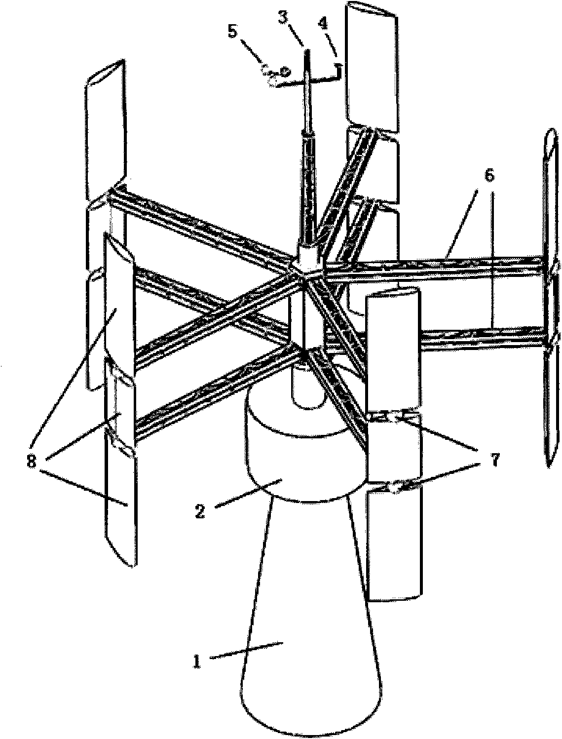
  • Megawatt-stage vertical shaft wind power generator with adjustable attack angle
  • Megawatt-stage vertical shaft wind power generator with adjustable attack angle
  • Megawatt-stage vertical shaft wind power generator with adjustable attack angle

Examples


Embodiment Construction

[0021] The implementation of the present invention will be further described below in conjunction with the accompanying drawings, but not as a limitation of the present invention.

[0022] The structure of this embodiment is as described above, combined with figure 1 , the main vertical shaft 1 of the present invention is fixed on the ground, the wind vane 4 and the anemometer 5 can rotate freely relative to their respective axes according to the actual wind direction, and the large blade 8 composed of a cantilever beam 6, a blade rotation device 7 and other accessories can be driven by the wind Under the action, it rotates independently relative to the main vertical shaft, and transmits the kinetic energy to the generator set 2, and the kinetic energy is converted into electrical energy by the generator.

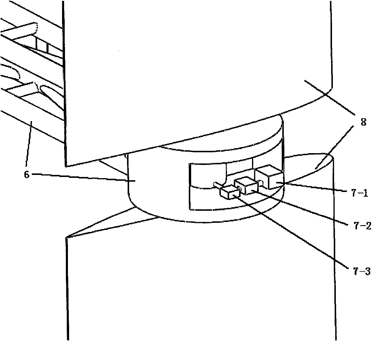
[0023] combine figure 2 , the blade rotation device 7 is described as follows: the pitch motor 7-1, the worm reduction box 7-2 and the pitch mechanism 7-3 with self-locki...


PUM


Abstract

The invention provides a megawatt-stage vertical shaft wind power generator with an adjustable attack angle. The vertical axis wind power generator comprises an electric power conversion device, a speed increasing box, a power generator, a variable pitch motor, a main vertical shaft, a cantilever cylinder, blade crossbeams, and blades with airfoils, wherein the cantilever cylinder is sleeved on the outer side of the main vertical shaft; the main vertical shaft is connected with the cantilever cylinder through a bearing; one end of each blade crossbeam is fixed on the cantilever cylinder, and blade autorotation devices are mounted at the other end of each blade crossbeam; a lightning rod is mounted at the top end of the main vertical shaft; an anemoscope is connected with an electronic control device; and the electronic control device controls the blade autorotation devices on each cantilever crossbeam, so as to enable the blades to adjust the windward angles according to a preset program and enable the power generator to be throughout in a state capable of producing the maximum torque. The starting wind speed is effectively reduced, and the wind energy utilization rate is increased.

Description

technical field [0001] The invention relates to a vertical-axis wind power generator, in particular to a blade rotation device applied to a vertical-axis wind power generator. Background technique [0002] A wind turbine, also known as a windmill, is an energy conversion device that converts wind energy into mechanical energy, electrical energy or thermal energy. According to the difference of the wind rotor axis, it can be divided into horizontal axis wind turbine and vertical axis wind turbine. The energy drive chain (ie wind wheel, main drive shaft, gearbox, generator) is in the horizontal direction, which is called a horizontal axis wind turbine. If the energy drive chain is in a vertical direction, it is called a vertical axis wind turbine. Vertical axis wind turbines can be divided into drag type and lift type. [0003] In the prior art, there are many public reports about generating devices utilizing wind energy, solar energy and their combination. However, the wi...

Claims


Application Information

Patent Timeline
Patent Type & Authority Applications(China)
IPC IPC(8): F03D9/00F03D3/06F03D7/06H02J3/38H01T19/04
CPCY02E10/763Y02E10/74Y02E10/72Y02E10/76
Inventor 杨寿生
Owner 杨寿生
Learn More