Annular steel plate assembling and welding method and device

A ring-shaped steel plate and assembly method technology, applied in auxiliary devices, welding equipment, welding equipment and other directions, can solve the problems of low degree of mechanization, complex assembly and welding process, no effective solutions, etc., to achieve efficient automatic production, improve overall efficacy effect

Active Publication Date: 2011-07-13
彭智祥
View PDF9 Cites 8 Cited by
  • Summary
  • Abstract
  • Description
  • Claims
  • Application Information

AI Technical Summary

Problems solved by technology

[0003] It can be seen that the current installation methods of many ring-shaped steel plates have the disadvantages of low degree of mechanization and complicated assembly and welding processes. There are also general-purpose equipment such as forklifts and cranes as auxiliary means, or special fixtures are used as auxiliary means, but only to a certain extent. It reduces the labor intensity and improves the manufacturing speed. In large-scale large-scale pipeline manufacturing projects, an efficient mechanized method is urgently needed to realize the rapid installation and welding of ring steel plates. For a long time, there is no effective solution to this technical problem.

Method used


Image

  • Annular steel plate assembling and welding method and device
  • Annular steel plate assembling and welding method and device
  • Annular steel plate assembling and welding method and device

Examples


Embodiment 1

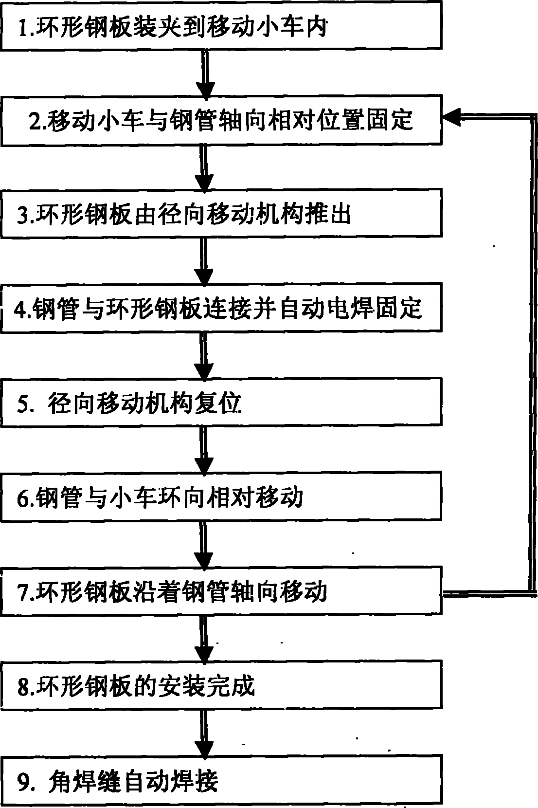
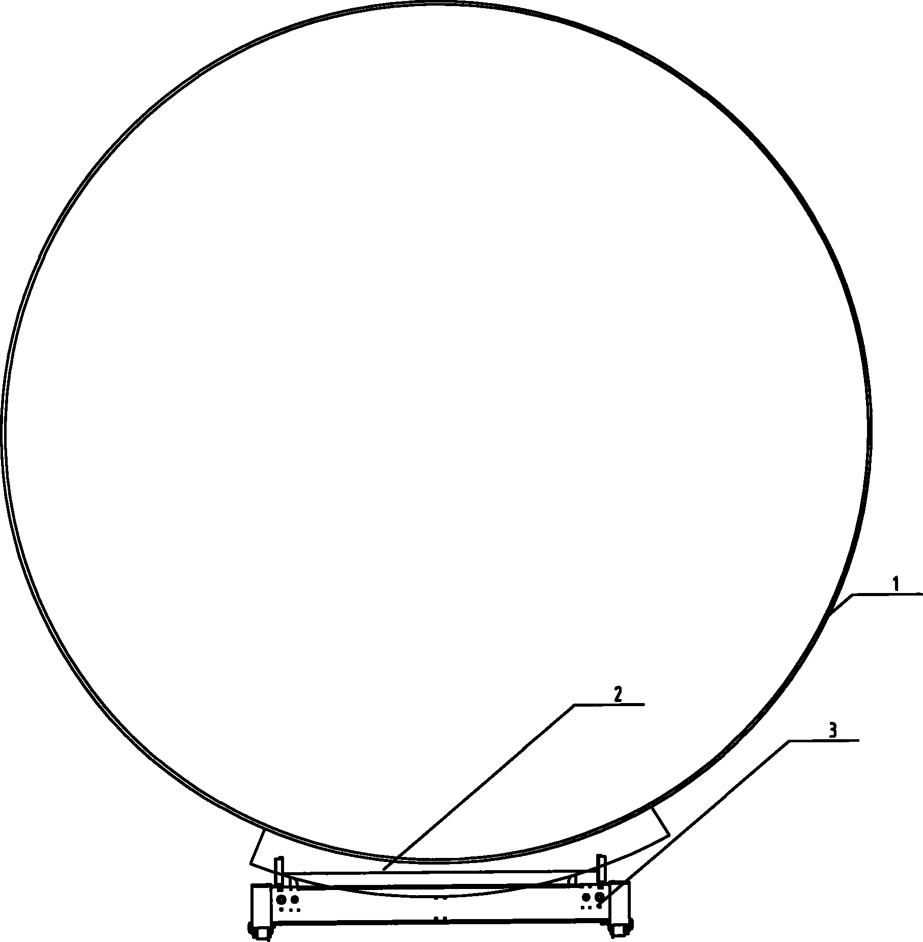
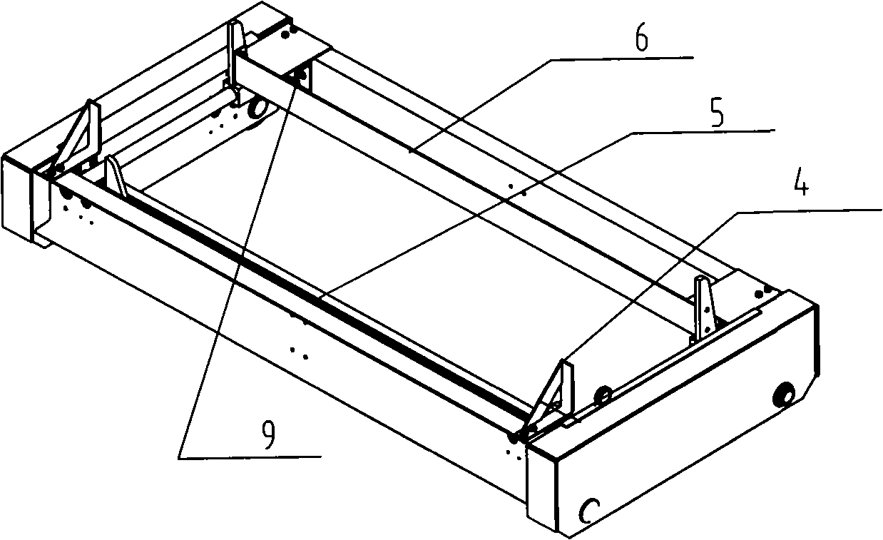
[0020] Embodiment 1: Carry out annular steel plate group welding at any place, as figure 2 , 3 , 4, and 5, the position of the steel pipe 1 is placed horizontally on the axis, and the ring-shaped steel plate 2 is transported to the bottom of the steel pipe with the rail trolley 3, and the steel pipe nozzle is used to limit the position where the trolley moves in the axial direction, so that a group of annular steel plates 2 are placed on the limit plate 4 The position of one end is just in the installation position of the structural design, start the radial movement mechanism 5, raise the annular steel plate 2 along the limit plate 4, and fit the steel pipe 1, fix the annular steel plate 2 by electric welding, and make the radial movement mechanism 5 times After arriving at the initial position, turn the steel pipe 1 for a section of the arc length of the annular steel plate 2, and start the axial movement mechanism 6 to move the remaining annular steel plate 2 as a whole for...

Embodiment 2

[0022] Embodiment 2: Carry out annular steel plate group welding in factory, as Figure 6 As shown, the steel pipe 1 is positioned vertically and fixedly on the axis, and the ring-shaped steel plate 2 is loaded by a trolley 3 that can be hung on the wall of the steel pipe 1, and transported to the upper part of the steel pipe 1 by a crane. , to limit the axial position of the trolley, the axial limit plate 4 defines the position of the upper end of the three sets of annular steel plates 2 just in the installation position of the structural design, start the radial movement mechanism 5, and move the annular steel plate along the position defined by the limit plate 4 Direction movement, fit with the steel pipe 1, fix the annular steel plate 2 by spot welding, make the radial movement mechanism 5 return to the initial position, then turn the trolley to pass a section of arc length of the annular steel plate 2, and start the hydraulic axial movement mechanism 6 to make the three T...


PUM


Abstract

The invention aims to provide an annular steel plate assembling and welding method and an annular steel plate assembling and welding device. In the invention, a method of positioning by the outer edge or outer wall of a steel tube, intensively transporting one or many groups of annular plates and automatically feeding is used to realize quick assembly, a special device for assembly has a structure capable of moving relative to the steel tube to realize functions such as quick positioning, pre-fastening, automatic welding, digital centralized control and the like. The device is compact in structure, simple in manufacturing and convenient for use.

Description

technical field [0001] The invention belongs to the field of mechanical manufacturing, and relates to a ring-shaped steel plate welding method and device, which are used to realize rapid assembly of ring-shaped steel plates. technical background [0002] In the process of manufacturing or installing large-scale pipelines and some tubular steel structures, it is necessary to assemble multiple annular steel plates into a complete reinforcement ring, and then weld the fillet welds. The existing methods mainly use manual installation when assembling annular steel plates, which requires labor. The intensity is high, the time is long, and the area occupied by the site is large. On the other hand, because most of the existing ring-shaped steel plates are welded by single-side welding, the welding speed is restricted, and deformation control problems exist during the welding process. Taking the Three Gorges water diversion steel pipe as an example, the ring steel plate of the press...

Claims


Application Information

Patent Timeline
Patent Type & Authority Applications(China)
IPC IPC(8): B23K37/04B23K9/12
Inventor 彭智祥李正江
Owner 彭智祥
Why Eureka
Try Eureka