Method for manufacturing metal sandwich glass

A technology of metal interlayer and manufacturing method, which is applied to parts of lighting devices, semiconductor devices of light-emitting elements, decorative arts, etc., can solve the problems of heavy weight, thick glass products, and damage to decorative effects, etc., and achieve light weight and thickness thin effect

Inactive Publication Date: 2012-11-21
LIGA PRECISION TECH
View PDF0 Cites 0 Cited by
  • Summary
  • Abstract
  • Description
  • Claims
  • Application Information

AI Technical Summary

Problems solved by technology

[0003] However, regardless of whether it is by painting or filming, although the pattern can be displayed on the glass product, because the pattern is formed on the surface of the glass, it is easy to be scratched by foreign objects and destroy the decorative effect. , some operators have launched glass products with patterned interlayers, such as figure 1 As shown, it mainly forms a pattern to be formed on a metal sheet 1 by etching, so that a plurality of etching grooves 2 will be formed on the metal sheet 1, and finally on the two sides of the metal sheet 1. Each side is provided with an adhesive film 3 and a glass layer 4, and the glass product with pattern interlayer can be completed. However, since the pattern on the metal sheet 1 is completed by etching, the thickness of the metal sheet 1 is at least will be greater than 0.15 mm, and both sides of the metal sheet 1 must be coated with the adhesive film 3 in order to glue the glass layer 4, so the thickness of the glass product will be thicker and the weight will be heavier. The cost of production will also be higher, without economic benefits, so the glass product with pattern interlayer still needs to be further improved

Method used


Image

  • Method for manufacturing metal sandwich glass
  • Method for manufacturing metal sandwich glass
  • Method for manufacturing metal sandwich glass

Examples


Embodiment Construction

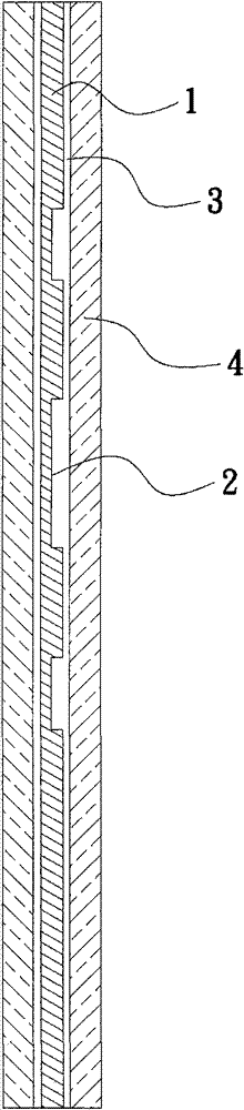
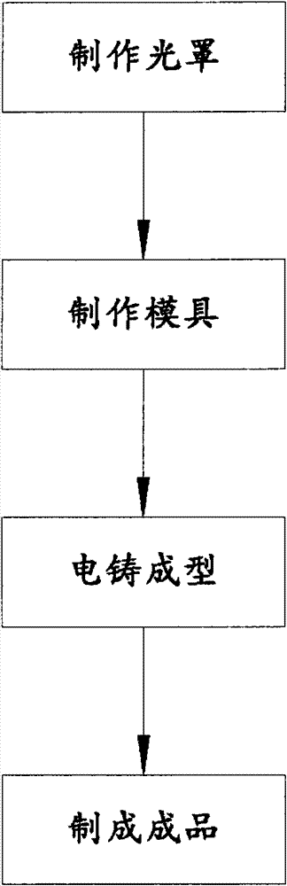
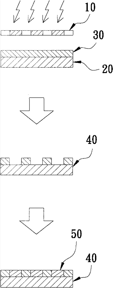
[0031] The manufacturing method of the present invention includes manufacturing steps such as making a photomask, making a mold, electroforming, and making a finished product. First, a pattern to be formed is made into a photomask, and then a photoresist is coated on a substrate. layer, and place the photomask on the top of the photoresist layer for exposure, so that the light-receiving part on the photoresist layer is cured, and then remove the uncured part of the photoresist layer to obtain a hollow pattern mold, and then, electroforming is performed through the mold to obtain a hollow metal film, and the hollow metal film will form a hollow pattern identical to the pattern, and finally, a glued film is pasted on at least one side of the hollow metal film , and attach a bottom layer and a glass layer to both sides of the hollowed-out metal film, and then pressurize and evacuate the hollowed-out metal film into the glued film, and pass the glued film between the bottom layer a...


PUM

PropertyMeasurementUnit
thicknessaaaaaaaaaa

Abstract

The invention discloses a method for manufacturing metal sandwich glass. The method comprises the steps of photomask manufacturing, mould manufacturing, electrotyping forming, finished product manufacturing, and the like. The method is characterized in that a hollow metal film can be formed between a bottom layer and a transparent glass layer, and the hollow metal film is formed into a hollow pattern, therefore, a particular hollow pattern can be presented on the metal sandwich glass, and compared with known techniques, the metal sandwich glass is thinner in thickness and lighter in weight, meanwhile, because the hollow metal film is arranged between the bottom layer and the glass layer, the hollow metal film can be protected by the bottom layer and the glass layer, thereby achieving the effects of resisting scratch and small possibility of wearing.

Description

technical field [0001] The invention relates to a glass structure, in particular to a method for making metal laminated glass. Background technique [0002] Due to the advantages of high hardness and high transparency, glass is widely used in building materials and decorations. In order to make glass products more distinctive and decorative, painting or filming is generally used. In this glass product It presents a pattern on the glass, giving the glass product a beautiful appearance. [0003] However, regardless of whether it is by painting or filming, although the pattern can be displayed on the glass product, because the pattern is formed on the surface of the glass, it is easy to be scratched by foreign objects and destroy the decorative effect. , some operators have launched glass products with patterned interlayers, such as figure 1 As shown, it mainly forms a pattern to be formed on a metal sheet 1 by etching, so that a plurality of etching grooves 2 will be formed ...

Claims


Application Information

Patent Timeline
Patent Type & Authority Patents(China)
IPC IPC(8): C03C27/00B44C5/04B44C5/08B44C3/02C25D1/10C25D1/04F21V33/00F21Y101/02F21Y115/10
Inventor 胡志坚王纪雯
Owner LIGA PRECISION TECH
Why Eureka
Try Eureka