
Universal water drain valve for air delivery pipe

A technology for drain valves and air pipes, applied to valve details, multi-way valves, valve devices, etc., which can solve problems such as inability to ensure the installation angle of drain valves and one-way valves, twisting, skewing, and malfunction of non-rigid air pipes, etc. , to achieve the effect of eliminating water storage in U-shaped tubes, preventing rupture and prolonging service life

Inactive Publication Date: 2012-09-05
YANGZHOU UNIV +1
View PDF0 Cites 0 Cited by
  • Summary
  • Abstract
  • Description
  • Claims
  • Application Information

AI Technical Summary

Problems solved by technology

Second, when the air compressor stops supplying air, the inlet of the air pipe is connected to the air, and the air pressure in the pipe drops to zero. At the end of the air pipe, water is poured into the air pipe to maintain the pressure balance inside and outside the pipe. However, due to the resistance of many U-shaped pipes Existence, the water cannot be poured back to the beginning of the gas pipeline near the bank of the reservoir, the gas pipeline will be flattened under the pressure of the external water, and if things go on like this, longitudinal cracks will be formed on both sides of the pipeline, causing the pipeline to rupture
The installation position and angle of these two valves on the pipeline have relatively high requirements. The non-rigid gas pipeline that sinks from the water surface will be torsion, skewed and other displacements during the sinking process, and the trap valve cannot be guaranteed after sinking to the bottom of the water. and the installation angle required by the one-way valve, the two valves will not work normally, and air leakage may also occur

Method used


Image

  • Universal water drain valve for air delivery pipe
  • Universal water drain valve for air delivery pipe
  • Universal water drain valve for air delivery pipe

Examples


Embodiment Construction

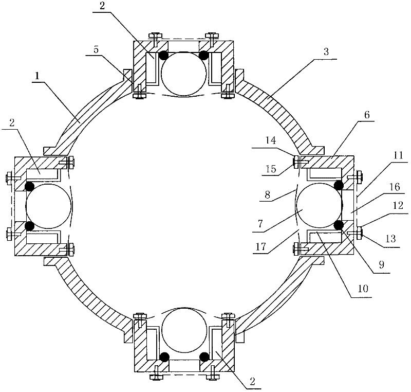
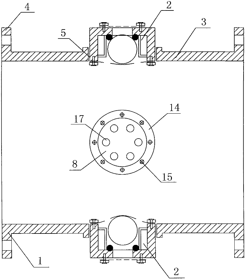
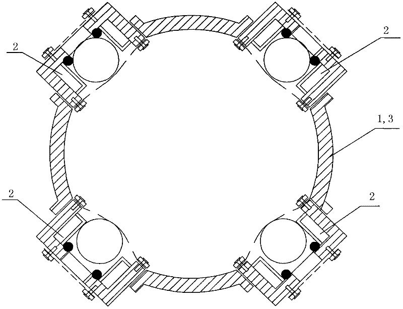
[0019] Such as figure 1 , figure 2 As shown, the universal drainage valve of the gas pipe is composed of a valve housing 1 and four valve cores 2. The valve casing 1 and the valve core 2 are both cylindrical, and the valve core 2 is vertically installed on the valve casing 1. The valve housing 1 is composed of a straight cylinder 3 and a flange 4. There are 4 valve core mounting holes 5 in the circumferential direction of the straight cylinder 3 for installing the valve core 2. The valve core 2 is fixed in the valve core installation hole 5 by threads. The valve housing 1 is connected to the gas pipe through flanges 4 at both ends. The valve housing 1 is made of metal or hard non-metallic materials. Spool 2 is composed of valve shoe 6, floating ball 7, elastic cover 8, O-ring 9, guide rod 10, filter screen 11, filter screen pressure ring 12, outer bolt 13, elastic cover pressure ring 14, and inner bolt 15. . The valve shoe 6 is in the shape of a round tube, one end is open...


PUM


Abstract

The invention relates to a universal water drain valve for an air delivery pipe, and belongs to the technical field of gate valves. A hollow cylindrical valve shell is annularly provided with at least four valve core installation holes and at least four valve cores; the valve cores are arranged in the valve core installation holes; and the axes of the valve cores are vertical to the axis of the valve shell. The valve has a scientific and reasonable structure and low cost and is easy to produce and manufacture and convenient to install and use; the valve is used for draining water from and feeding water into an underwater non-rigid air delivery pipe under complicated installation conditions, and can work at any transverse and longitudinal installation angle; when the pipe delivers air, thevalve removes accumulated water from the pipe, avoids the phenomenon that water exists in a U-shaped pipe due to gas and the water in the pipe, reduces air delivery pressure and saves energy; when the pipe stops delivering the air and relieves the pressure, the valve allows external water to enter the pipe, keeps internal pressure and external pressure balanced, prevents the pipe from being deformed and broken due to the external pressure, and prolongs the service life of the air delivery pipe; and a filter screen is covered on the outer side of a water inlet and outlet of each valve core, sothat floating objects in the water are prevented from entering the valve shell, and impurities in the water are prevented from influencing the sealing property of the valve cores and the air deliveryefficiency of the air delivery pipe.

Description

Technical field [0001] The invention relates to a gas pipeline drainage valve, in particular to a gas pipeline drainage valve in a complicated underwater installation environment. Background technique [0002] Oxygenating and mixing equipment such as water-lifting aerators and stratospheric aerators are installed in reservoirs and lakes to improve the water quality of reservoirs and lakes. The oxygenation mixing equipment uses compressed air as the gas source, and is supplied by an air compressor installed on the shore through an underwater gas pipe. When installing a gas pipe in a large body of water, it is impossible to drain the water and install it under the water. Instead, tie the weight and sink to the bottom after the water surface takes over the pipe. Due to the complicated underwater terrain and undulations, only flexible pipelines such as low-density polyethylene pipes and rubber pipes can be used. The installed pipelines also fluctuate with the terrain. The beginning...

Claims


Application Information

Patent Timeline
Patent Type & Authority Patents(China)
IPC IPC(8): F16K11/22F16K31/20
Inventor 丛海兵黄廷林
Owner YANGZHOU UNIV
Learn More