Phase change heat accumulating defrosting system for air source heat pump water heater

An air source heat pump and phase change heat storage technology, which is applied in the types of heat exchangers, heat storage equipment, indirect heat exchangers, etc. The effect of avoiding low-voltage protection shutdown

Inactive Publication Date: 2011-07-20
SOUTH CHINA UNIV OF TECH
View PDF6 Cites 25 Cited by
  • Summary
  • Abstract
  • Description
  • Claims
  • Application Information

AI Technical Summary

Problems solved by technology

[0004] The purpose of the present invention is to overcome the shortcomings and deficiencies of the prior art, and to provide a phase change thermal storage defrosting system for air source heat pump water heaters. Insufficient defrosting heat caused by poor defrosting reliability, large energy consumption loss, poor operation effect and other problems; the defrosting process of the present invention does not need to absorb heat from the heating space, and uses the system waste heat of the heat pump water heater and the waste water waste heat of the shower room to defrost Frost

Method used


Image

  • Phase change heat accumulating defrosting system for air source heat pump water heater
  • Phase change heat accumulating defrosting system for air source heat pump water heater
  • Phase change heat accumulating defrosting system for air source heat pump water heater

Examples


Embodiment approach 1

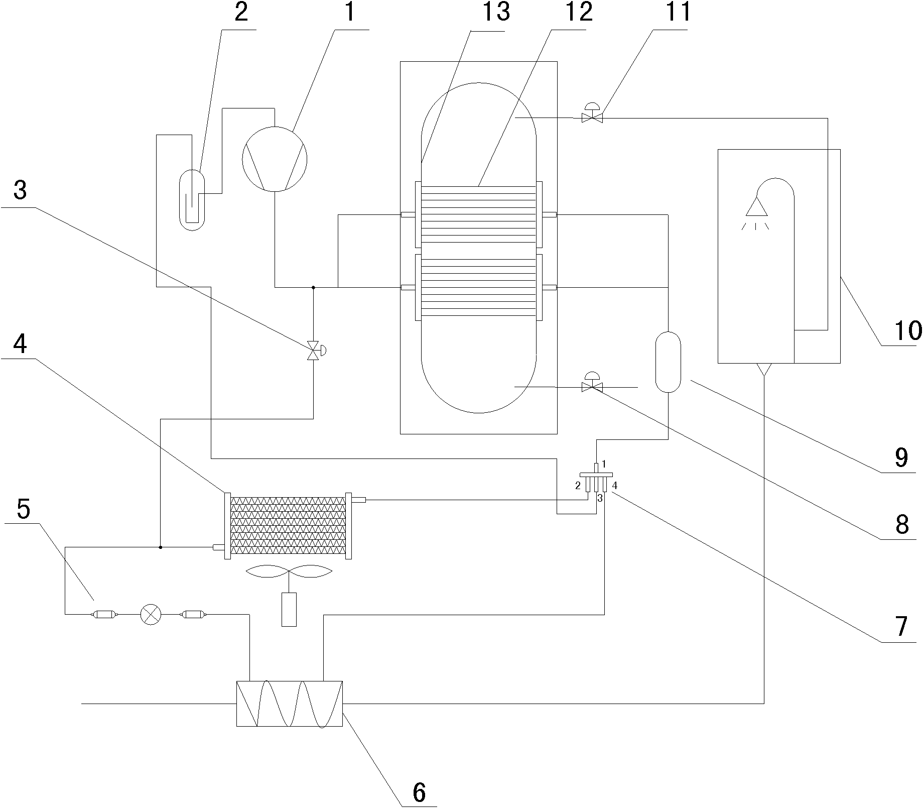
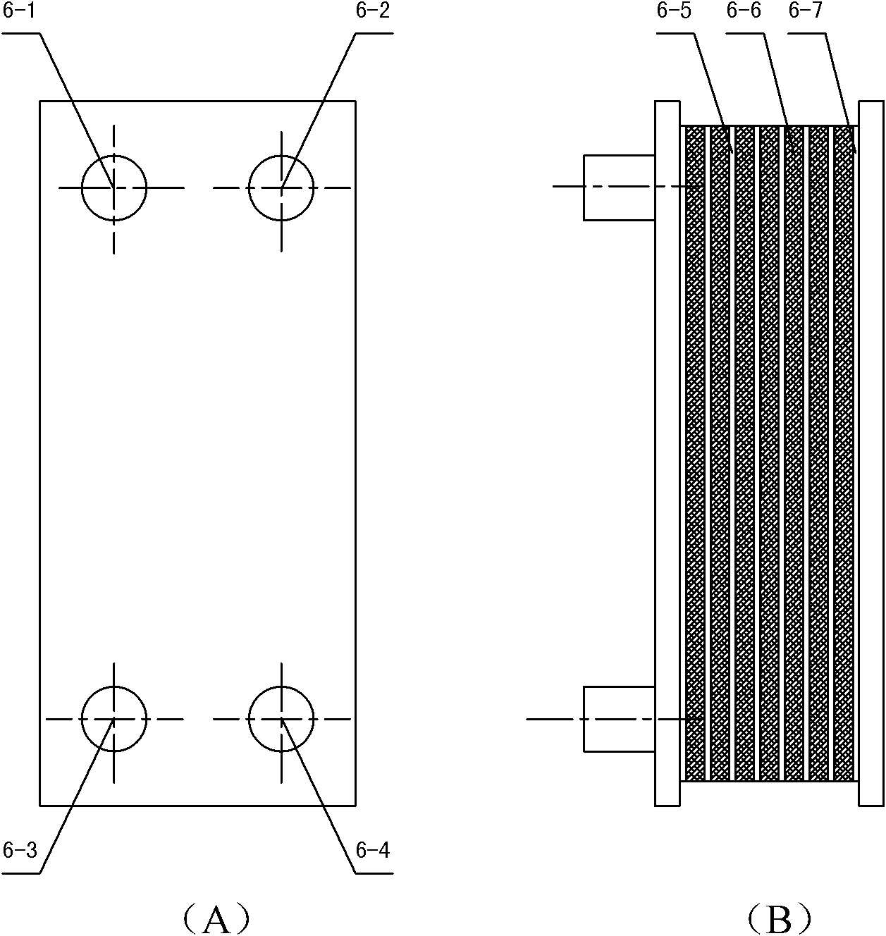
[0023] Implementation Mode 1: Combining figure 1 , figure 2 , the phase change heat storage type defrosting system of the air source heat pump water heater of the present invention comprises a compressor 1, a gas-liquid separator 2, a one-way solenoid valve 3, an outdoor heat exchanger 4, a capillary tube 5, a four-way reversing valve 7, Drying filter 9, external water tank heat exchanger 12, water storage tank 13; the outlet nozzle of the compressor 1 and one end nozzle of the one-way solenoid valve 3 are connected to one end nozzle of the external water tank heat exchanger 12, The input port of the compressor 1 is connected to the output port of the gas-liquid separator 2, the other end of the external water tank heat exchanger 12 is connected to one end of the dry filter 9, and the other end of the one-way solenoid valve 3 One end of the nozzle and the capillary tube 5 is connected to one end of the outdoor heat exchanger 4, the input nozzle of the gas-liquid separator 2 ...

Embodiment approach 2

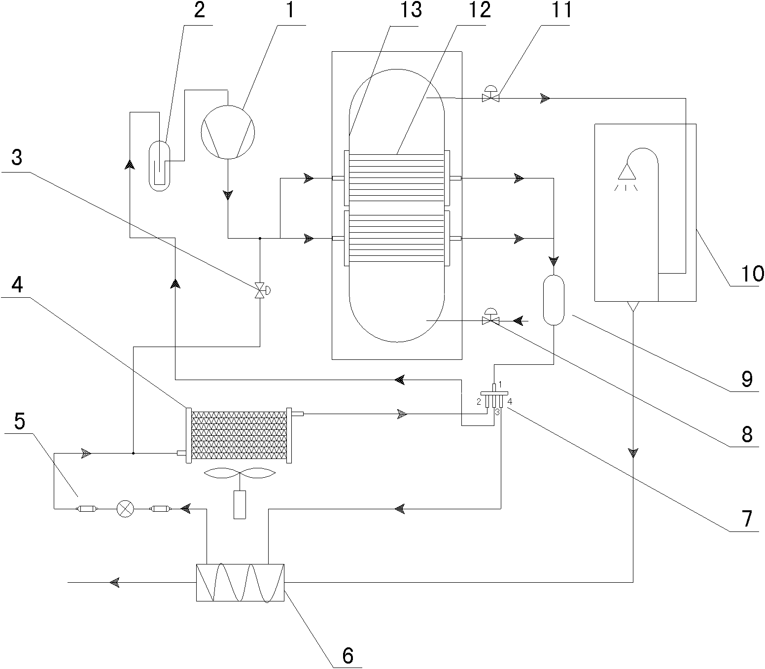
[0048] Implementation Mode 2: Combining figure 1 , figure 2 , image 3 , Explain the working process of waste heat energy storage of the heat storage type defrosting system of the above-mentioned air source heat pump water heater (such as image 3 ).

[0049] The difference from Embodiment 1 is that when the system is in the working state of waste heat energy storage, the system enters from the first input and output port of the four-way reversing valve 7 to the fourth input and output port of the four-way reversing valve 7, and then sequentially After the phase change heat accumulator 6, the capillary tube 5, and the outdoor heat exchanger 4, it returns to the second input and output port of the four-way reversing valve 7, that is, the circulation path of the four-way reversing valve is 1-4-2-3 . The first cut-off valve 8 and the second cut-off valve 11 communicate internally. Other components and connections are the same as those in Embodiment 1.

[0050] When the sys...

Embodiment approach 3

[0051] Implementation Mode Three: Combining figure 1 , figure 2 , Figure 4 , Explain the heat storage type defrosting system release energy defrosting working process of the above-mentioned air source heat pump water heater (such as Figure 4 ).

[0052] The difference from Embodiment 1 is that when the system is in the working state of energy release and defrosting, the system enters from the first input and output port of the four-way reversing valve 7 to the second input and output port of the four-way reversing valve 7, and then After passing through the outdoor heat exchanger 4, capillary tube 5, and phase change heat accumulator 6 in turn, it returns to the fourth input and output port of the four-way reversing valve 7, that is, the circulation path of the four-way reversing valve is 1-2-4- 3. The first cut-off valve 8 and the second cut-off valve 11 communicate internally. Other components and connections are the same as those in Embodiment 1.

[0053] When the ...


PUM


Abstract

The invention discloses a heat accumulating defrosting system for an air source heat pump water heater. The system comprises a compressor, a gas-liquid separator, a four-way reversing valve, an outdoor heat exchanger, a capillary, a plate-type phase change heat accumulator, a one-way electromagnetic valve, a dry filter, a first stop valve, a shower room, a second stop valve, an external water tank heat exchanger and a water storage tank. The defrosting process comprises that: condensed waste heat of the heat pump water heater system and wastewater waste heat of the shower room are reclaimed through the phase change heat accumulator, and the flowing direction of a refrigerant in the plate-type phase change heat accumulator and the outdoor heat exchanger is changed by steering of the four-way reversing valve, so that switching of functions of waste heat energy accumulation and energy release defrosting of the system is realized. The system has simple structure and is convenient to control and easy to maintain and the like.

Description

technical field [0001] The invention relates to the technical field of refrigeration equipment, in particular to a phase-change thermal storage defrosting system for an air-source heat pump water heater. Background technique [0002] When the air source heat pump is in heating operation in winter, the air-side heat exchanger acts as an evaporator. Due to the low ambient temperature, the temperature on the surface of the heat exchanger also drops, even lower than 0°C. When the outdoor air flows through the heat exchanger When the heater coil is heated, the moisture contained in it will precipitate out and form a frost layer. The frost layer increases the heat conduction resistance, reduces the heat transfer coefficient of the heat exchanger, and reduces the air flow through the heat exchanger. As the frost layer thickens, there will be a drop in evaporation temperature, a drop in heating capacity, and attenuation of fan performance. It will affect the heating efficiency, an...

Claims


Application Information

Patent Timeline
Patent Type & Authority Applications(China)
IPC IPC(8): F25B47/00F28D20/02
CPCY02E60/145Y02E60/14
Inventor 巫江虹游少芳
Owner SOUTH CHINA UNIV OF TECH
Why Eureka
Try Eureka