
Dynamic angle measurement error detector used in photo-electric axial angle encoder

A shaft angle encoder and encoder technology, applied in the direction of instruments, etc., can solve the problem that the dynamic performance cannot be verified, and achieve the effect of only testing the static angle measurement accuracy

Inactive Publication Date: 2011-07-20
INST OF OPTICS & ELECTRONICS - CHINESE ACAD OF SCI
View PDF3 Cites 34 Cited by
  • Summary
  • Abstract
  • Description
  • Claims
  • Application Information

AI Technical Summary

Problems solved by technology

As the core precision angle measurement unit and speed feedback unit, the photoelectric shaft encoder directly affects the measurement accuracy and tracking performance of photoelectric precision tracking measurement, photoelectric observation and identification of astronomical targets, and the static accuracy and low speed of the photoelectric shaft encoder. The high accuracy has been proven in practice for many years, but its dynamic performance (dynamic angle measurement accuracy) has not yet been verified under the condition of high working angular velocity. In order to ensure the dynamic measurement accuracy and dynamic tracking performance of the new generation of instruments and equipment , it is urgent to solve the testing problem of dynamic angle measurement accuracy of photoelectric shaft angle encoder

Method used


Image

  • Dynamic angle measurement error detector used in photo-electric axial angle encoder
  • Dynamic angle measurement error detector used in photo-electric axial angle encoder
  • Dynamic angle measurement error detector used in photo-electric axial angle encoder

Examples


Embodiment Construction

[0018] In order to make the object, technical solution and advantages of the present invention clearer, the present invention will be described in further detail below in conjunction with specific embodiments and with reference to the accompanying drawings.

[0019] This embodiment introduces the specific implementation method of the photoelectric shaft angle encoder dynamic detector.

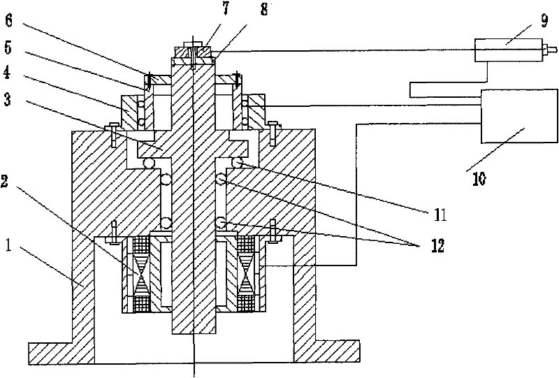
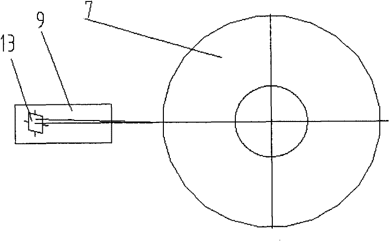
[0020] figure 1 A schematic diagram of the photoelectric shaft encoder dynamic detector is shown, figure 1 It includes a base 1, a torque motor with a speed measuring machine 2, a rotating shaft 3, a fixed part of the encoder under test 4, a rotating part of the encoder under test 5, a coupling 6, a polyhedron 7, a polyhedron seat 8, a dynamic Sending autocollimator 9, computer control and processing unit 10; the fixed part 4 of the encoder under test is installed on the base 1, the rotating part 5 of the encoder under test is connected to the rotating shaft 3 through the holding device of the...


PUM


Abstract

The invention relates to a dynamic angle measurement error detector used in a photo-electric axial angle encoder. A fixation part of a to-be-tested encoder is arranged on a base of the detector, a rotary part of the to-be-tested encoder is connected with a revolving shaft by a coupling joint, a polyhedron is fixed on the revolving shaft of the detector, a dynamic signaling autocollimation aims at a reflecting surface of the polyhedron, and a rotator of a torque motor is connected with the revolving shaft. During the detection, the torque motor is controlled by a computer to continuously rotate at a certain speed, and the revolving shaft, the rotary part of the to-be-tested encoder and the polyhedron are driven to rotate by the torque motor. When one operating angle of the polyhedron is turned, and the operating surface of the polyhedron is perpendicular to an optical axis, a trigger circuit sends out trigger impulses. Encoder values can be sampled after a data acquisition system probes trigger impulse signals. After the rotary part of the to-be-tested encoder rotates a circle, a group of sampling values can be obtained, and dynamic angle measurement errors of the to-be-tested encoder can be calculated by a data-processing system of the computer. The dynamic angle measurement error detector can be used for detecting the dynamic errors of the photo-electric axial angle encoder and has higher precision.

Description

technical field [0001] The invention relates to a precision detector for geometric quantities, in particular to a detector for dynamic angle measurement errors of photoelectric shaft angle encoders. Background technique [0002] Photoelectric precision tracking measurement, photoelectric observation and recognition technology of astronomical targets are the key technologies. In these fields, a number of significant and significant achievements have been achieved. After nearly 20 years of hard work, especially the rapid development of the past 10 years, photoelectric precision tracking measurement, astronomical target photoelectric observation and identification technology has developed from the primary stage to a higher technology stage, and is currently actively carrying out the research and development of a new generation of instruments and equipment. Tackling key problems. Since the speed of the target to be tested is getting faster and faster (aircraft, missiles, etc.),...

Claims


Application Information

Patent Timeline
IPC IPC(8): G01D18/00
Inventor 杨文志曹学东景洪伟许玮琦
Owner INST OF OPTICS & ELECTRONICS - CHINESE ACAD OF SCI
Learn More