

Sample sending and taking manipulator for industrial analyzer
An industrial analyzer and sampling technology, applied in the field of industrial analyzers, can solve the problems of temperature loss of combustion device 16, reduce measurement accuracy, improve energy consumption, etc., achieve simple and compact structure, improve overall performance, and reduce opening size. Effect
- Summary
- Abstract
- Description
- Claims
- Application Information
AI Technical Summary
Problems solved by technology
Method used
Image

Examples
Embodiment Construction
[0022] The present invention will be further described in detail below in conjunction with the accompanying drawings and specific embodiments.
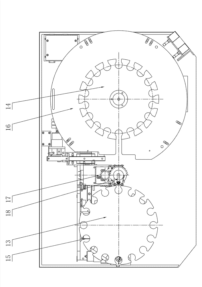
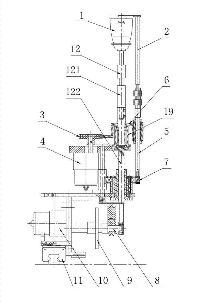
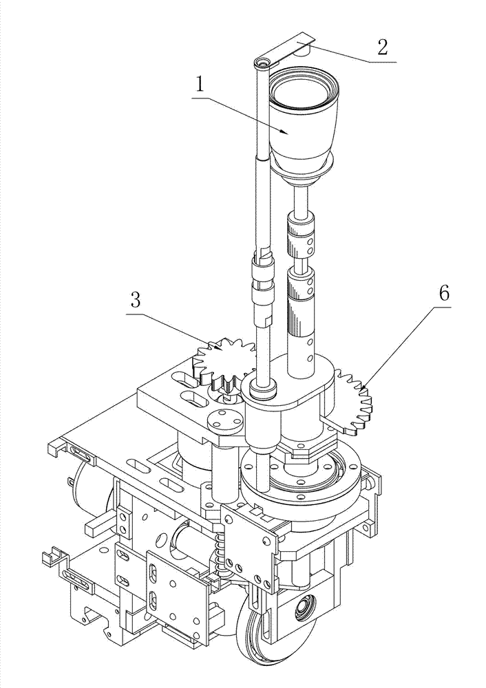
[0023] Such as figure 2 and image 3 As shown, the sampling manipulator for industrial analyzers of the present invention includes a crucible support assembly and a crucible clamp assembly. The crucible support assembly includes a crucible support shaft 12 and a lifting motion drive assembly and a horizontal motion drive assembly positioned at the bottom of the crucible support shaft 12. The crucible clamp The assembly includes a crucible clamp 2 and a crucible clamp support shaft 5. The crucible support shaft 12 includes a rotating section 121 and a fixed section 122 from top to bottom. The crucible clamp assembly also includes a rotating assembly that makes the crucible clamp support shaft 5 and the rotating section 121 rotate together. . Through this rotating assembly, the crucible clamp assembly can always be in the direction w...
PUM
 Abstract
Description
Claims
Application Information