Arm type current collector

A collector and arm type technology, applied in the field of improvement of tension collectors, can solve problems such as large maintenance workload and achieve the effect of smooth distribution

Inactive Publication Date: 2011-07-20
江苏江鹤滑线电气有限公司
View PDF9 Cites 0 Cited by
  • Summary
  • Abstract
  • Description
  • Claims
  • Application Information

AI Technical Summary

Problems solved by technology

This requires a large amount of maintenance work

Method used


Image

  • Arm type current collector
  • Arm type current collector
  • Arm type current collector

Examples


Embodiment Construction

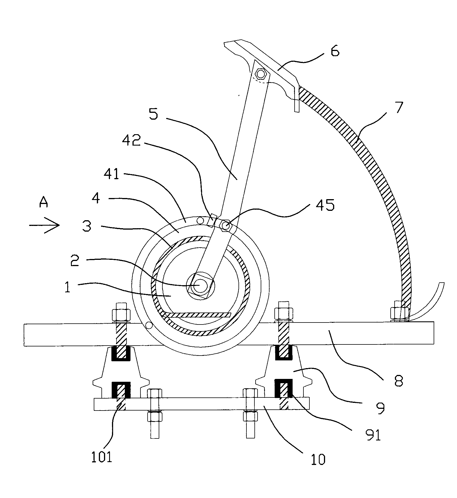
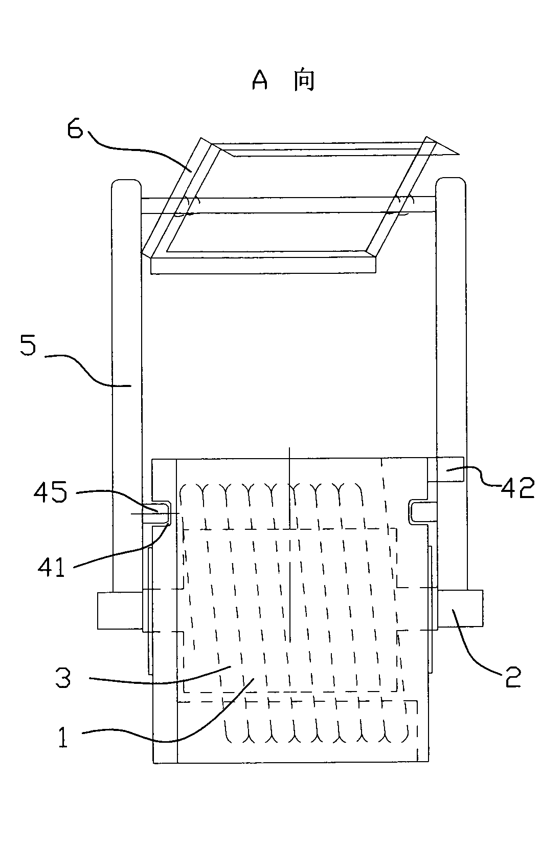
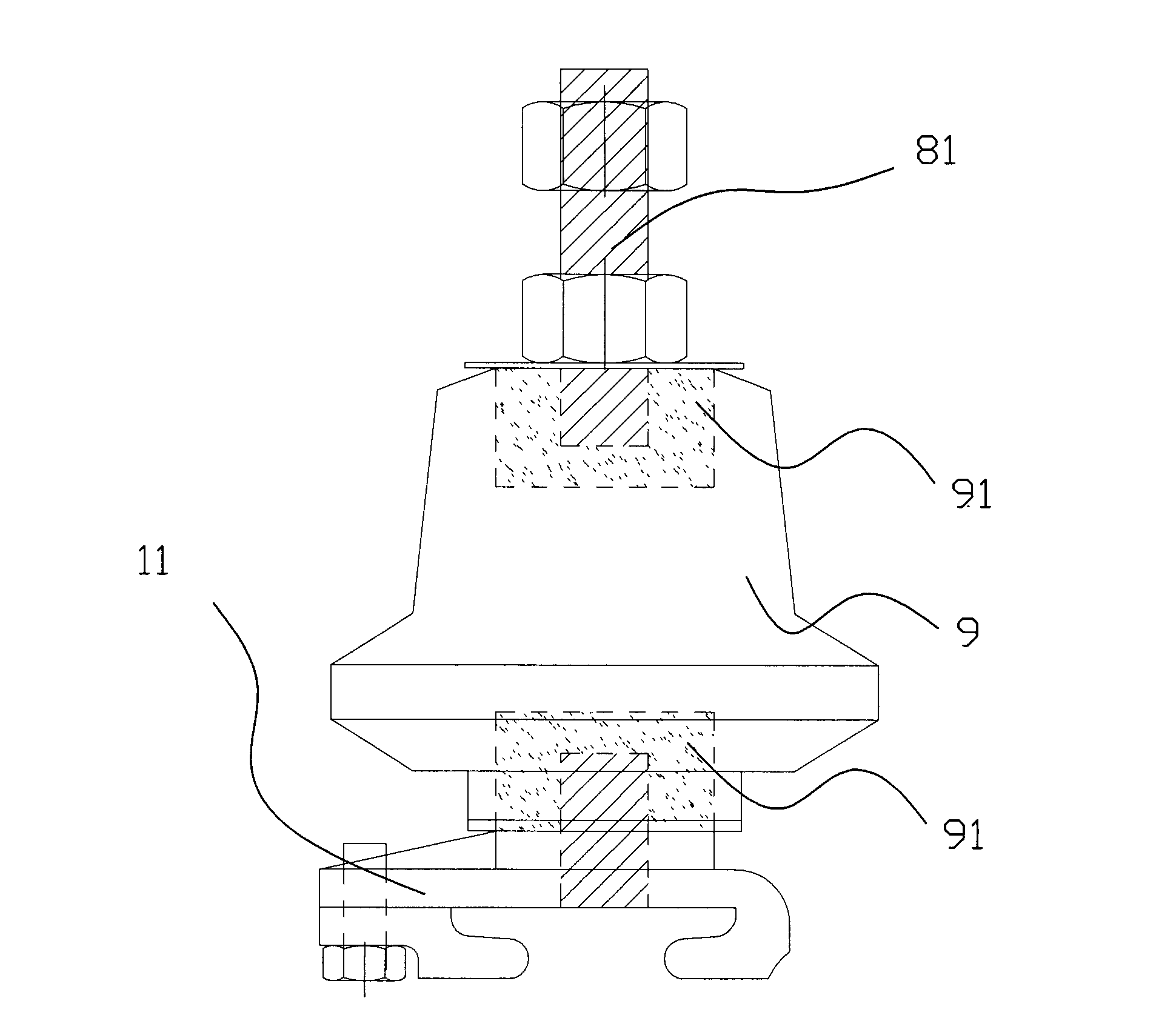
[0017] The present invention as Figure 1-3 As shown, it includes an outer cylinder 4, an inner cylinder 1, a torsion spring 3 arranged between the outer cylinder 4 and the inner cylinder 1, a rotating arm 5, a brush 6, a cable connection column, and a flexible cable connected to the cable connection column. Conductive strip 7, base plate 8 and seat plate 10, the brush 6 is movably connected to the head end of the rotating arm 5, the outer cylinder 4 is fixedly connected with the base plate 8 as a whole, the outer cylinder 4 The end face is provided with a circle of grooves 41 . When specifically making the connected outer cylinder 4 and base plate 8, the integral molding method is adopted, and a part of the outer cylinder 4 is "sinked" into the lower part of the base plate 8, which can further reduce the overall height, and is more convenient to bear the torsion spring 3 of elasticity.

[0018] The tail end of the rotating arm 5 is connected to the shaft head 2 of the inner...


PUM


Abstract

The invention discloses an arm type current collector which relates to improvement on a tension current collector, reduces the probability that an electric brush goes off rails, and avoids complete release of a torsion spring. The arm type current collector comprises an outer cylinder, an inner cylinder, a torsion spring, a rotating arm, an electric brush, a cable connecting column, a soft conductive band, a bottom plate and a seat plate, wherein the torsion spring is arranged between the outer cylinder and the inner cylinder; the soft conductive band is connected with the cable connecting column; the electric brush is movably connected to the head end of the rotating arm; the outer cylinder is fixedly connected with the bottom plate into a whole; the end face of the outer cylinder is provided with a ring of groove; the tail end of the rotating arm is connected to an axial end of the inner cylinder; the arm body of the rotating arm, corresponding to the groove of the outer cylinder, is provided with a guide pin which extends into the groove; and a phase block for limiting the running range of the guide pin is arranged in the groove on the end face of the outer cylinder. The phase block can limit the rotation of the rotating arm within 360 degrees, namely the tensile force of the torsion spring can be restored by only simply pulling the rotating arm back, so that contact tension between the electric brush and a wire / rail of an electrical appliance is guaranteed. In addition, the rotating arm can be turned to adjust the elastic force of the torsion spring.

Description

technical field [0001] The invention relates to a current collector for picking up electric energy at the collector side in a trolley line system, in particular to an improvement on a tension collector. Background technique [0002] The trolley line collector is the main device for picking up electric energy on the collector side of the trolley line system. It transmits electric energy directly to the electrical appliances through the sliding contact between the collector brush and the guide rail, so as to realize the mobile power supply of the system. The trolley line collector is composed of two parts: the tension device of the mechanical structure and the collector brush directly in sliding contact with the guide rail. [0003] The tension device of the mechanical structure determines the sliding contact pressure between the collector brush and the guide rail and the stability of the mechanism, and the collector brush is the conductor for the guide rail to pick up electri...

Claims


Application Information

Patent Timeline
IPC IPC(8): H01R39/02H01R39/18
Inventor 华鹤章董永军
Owner 江苏江鹤滑线电气有限公司
Why Eureka
Try Eureka