Control method of proportional valve output compensation circuit

A control method and output compensation technology, which is applied to output power conversion devices, control/regulation systems, DC power input conversion to DC power output, etc., can solve problems such as battery voltage fluctuations, and achieve a simple, reliable and easy-to-implement circuit Effect

Active Publication Date: 2013-07-17
JIANGSU XCMG CONSTR MASCH RES INST LTD
View PDF5 Cites 0 Cited by
  • Summary
  • Abstract
  • Description
  • Claims
  • Application Information

AI Technical Summary

Problems solved by technology

[0003] The purpose of the present invention is to provide a control method of a proportional valve output compensation circuit to solve the problem that the output of the power supply provided by the battery will fluctuate with the voltage of the battery

Method used


Image

  • Control method of proportional valve output compensation circuit
  • Control method of proportional valve output compensation circuit

Examples


Embodiment 1

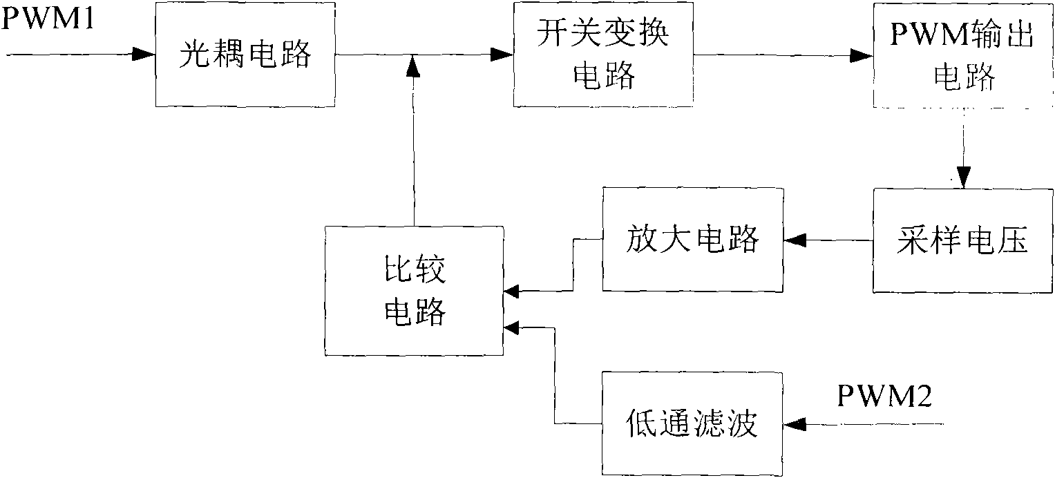
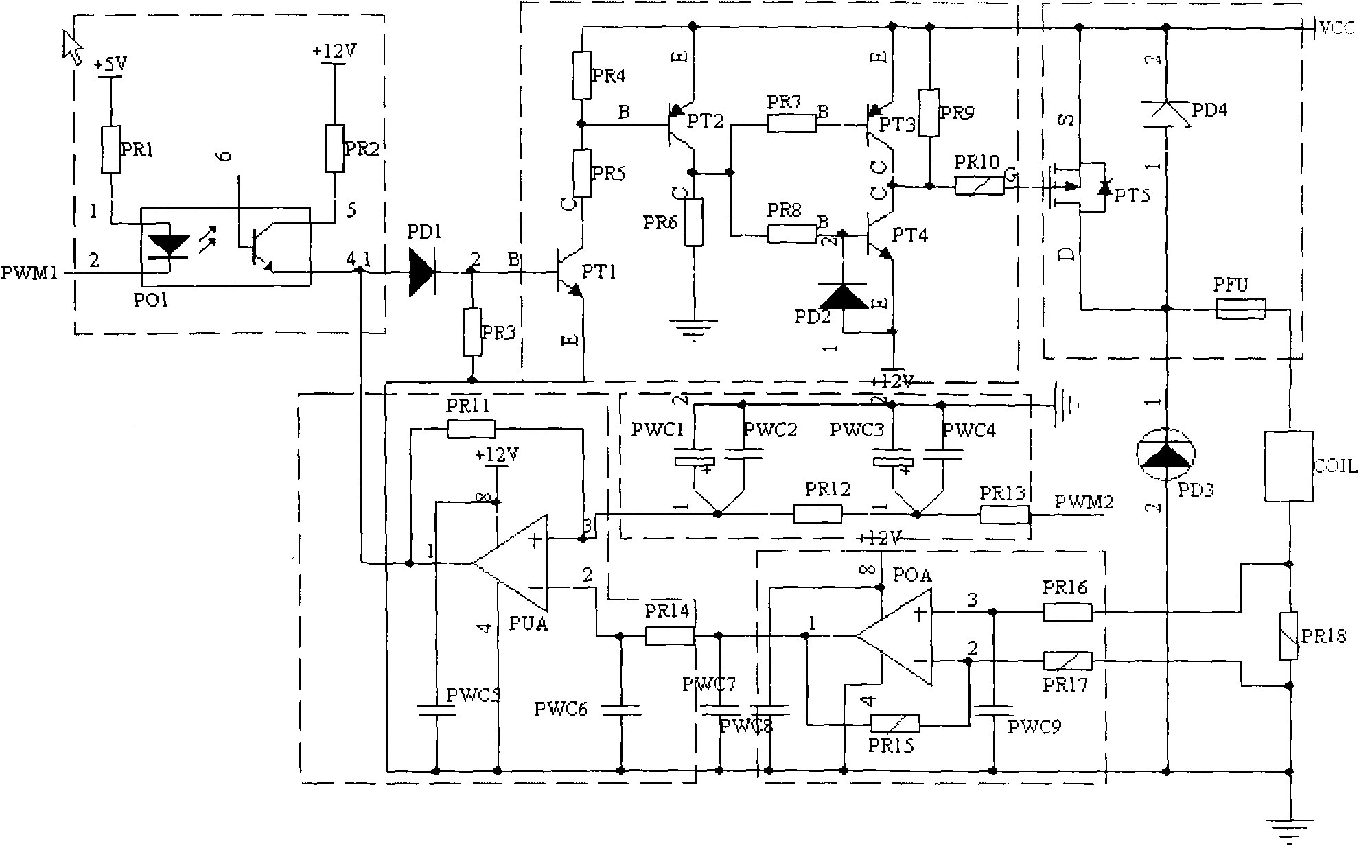
[0010] Embodiment 1: the compensation circuit comprises an optocoupler circuit, a switching conversion circuit, a PWM output circuit, a sampling circuit, an amplifying circuit, a low-pass filter and a comparison circuit, and the output terminal of the optocoupler circuit and the output terminal of the comparison circuit are simultaneously transformed with the switch The input end of the circuit is connected, the output end of the switch circuit is connected with the input end of the PWM output circuit, the output end of the PWM output circuit is connected with the input end of the sampling circuit, the output end of the sampling circuit is connected with the input end of the amplifying circuit, and the output end of the amplifying circuit is connected The output terminal and the output terminal of the low-pass filter are simultaneously connected to the input terminal of the comparison circuit.

[0011] The control method of the compensation circuit is: the PWM1 signal generated...


PUM


Abstract

The invention relates to a proportional valve output compensation circuit and a control method, belonging to a proportional valve output circuit of which the power is supplied by a storage battery on engineering machinery. The compensation circuit comprises an optical coupling circuit, a switching and converting circuit, a PWM (Pulse-Width Modulation) output circuit, a sampling circuit, an amplifying circuit, a low-pass filter and a comparison circuit, wherein the output end of the optical coupling circuit is connected with the output end of the comparison circuit and the input end of the switching and converting circuit; the output end of the switching circuit is connected with the input end of the PWM output circuit; the output end of the PWM output circuit is connected with the input end of the sampling circuit; the output end of the sampling circuit is connected with the input end of the amplifying circuit; and the output end of the amplifying circuit is connected with the output end of the low-pass filter and the input end of the comparison circuit. The invention has the advantages that the output circuit of a proportional valve coil is sampled, amplified and compared and then fed back to the output end of an optical coupler, thereby realizing current negative feedback, and the circuit is simple, reliable and easy to realize.

Description

technical field [0001] The invention relates to a proportional valve output circuit used in engineering machinery powered by a storage battery, in particular to a control method for the proportional valve output compensation circuit. Background technique [0002] The power supply voltage of construction machinery is provided by the battery, and the battery voltage will fluctuate up and down. The fluctuation of the battery voltage has a certain relationship with the power of the battery. When the power is sufficient, the voltage is high, and when the power is insufficient, the voltage is low. At the same time, the battery voltage will also vary with the load. Then, the output of the proportional valve powered by the battery voltage will fluctuate with the level of the battery voltage, which will affect the output effect of the proportional valve. Contents of the invention [0003] The purpose of the present invention is to provide a control method of a proportional valve ...

Claims


Application Information

Patent Timeline
Patent Type & Authority Patents(China)
IPC IPC(8): H02M3/156
Inventor 魏彬胡传正温读夫李党伟孟庆勇范旭辉
Owner JIANGSU XCMG CONSTR MASCH RES INST LTD
Why Eureka
Try Eureka