Eureka AIR delivers breakthrough ideas for toughest innovation challenges, trusted by R&D personnel around the world.

Rubber track and track type traveling body

一种橡胶履带、行驶体的技术,应用在橡胶履带及履带式行驶体领域,能够解决大剪切应变、龟裂、弯曲刚性差异等问题

Inactive Publication Date: 2011-07-20
BRIDGESTONE CORP
View PDF2 Cites 3 Cited by
  • Summary
  • Abstract
  • Description
  • Claims
  • Application Information

AI Technical Summary

Problems solved by technology

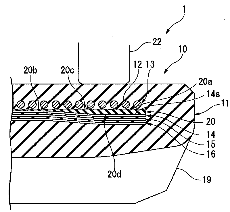
[0007] However, in the above-mentioned conventional rubber crawler, during running, the lower part of the inner peripheral surface of the rubber crawler on the ground side is pressed against the ground by the roller, so that the bending rigidity of the steel cord layer and the diagonal reinforcement layer are different. Accordingly, at a position corresponding to the end of the innermost reinforcing layer in the track width direction between the innermost reinforcing layer on the innermost peripheral side and the steel cord layer among the plurality of diagonal reinforcing layers, Larger shear strains lead to cracking

Method used


Image

  • Rubber track and track type traveling body
  • Rubber track and track type traveling body
  • Rubber track and track type traveling body

Examples


Embodiment Construction

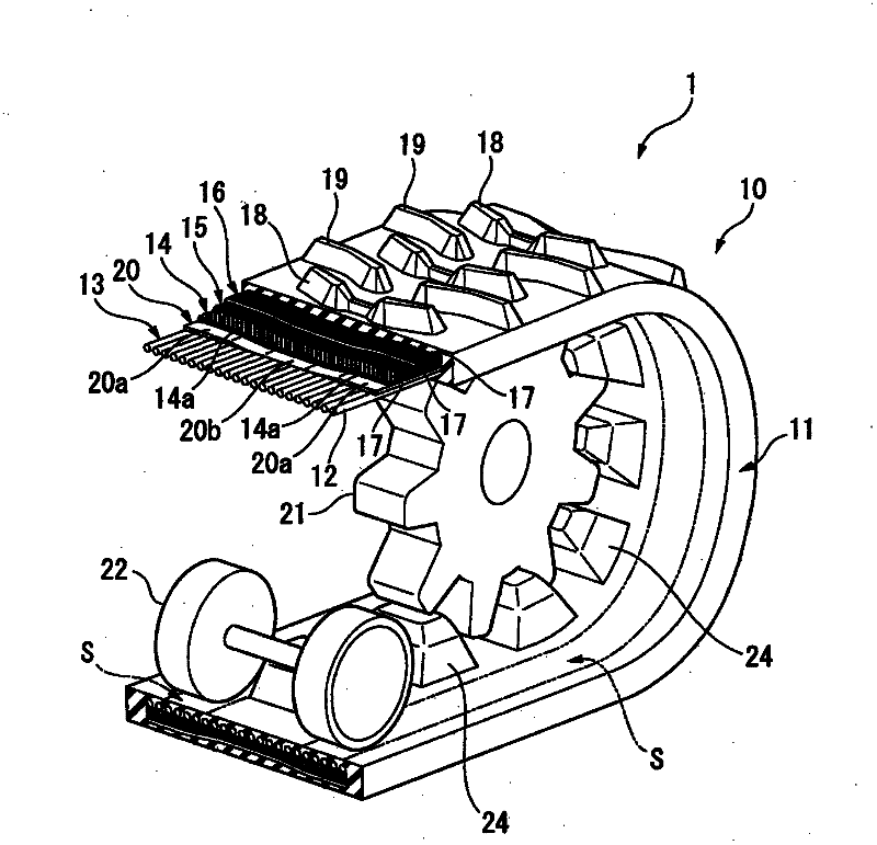
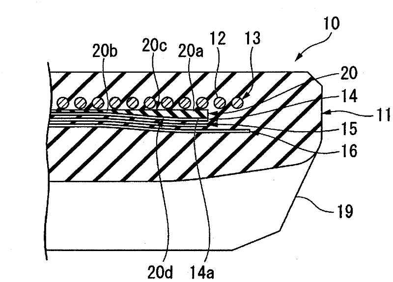
[0027] Below, refer to figure 1 and figure 2 One embodiment of the rubber crawler of the present invention will be described.

[0028] like figure 1 As shown, on the left and right pairs of crawler running bodies 1 disposed on the bottom of construction machinery such as hydraulic excavators, agricultural machinery, and other crawler vehicles, respectively, there are: driving wheels 21; driven wheels not shown in the figure; The rubber crawler 10 wound between the above two wheels in an endless belt shape; the pair of left and right roller passing surfaces S formed on the inner peripheral surface of the rubber crawler main body 11 of the rubber crawler 10 is arranged and along with the rubber crawler 10 The feeding movement of the rubber track 10 rolls a plurality of rollers 22 . In addition, in the illustrated example, the rubber crawler 10 is a so-called coreless rubber crawler in which a core is not embedded.

[0029] The driving wheel 21 is a sprocket, and is rotatabl...


PUM


Abstract

A rubber track comprising a steel cord layer (13) formed by embedding steel cords in an endless belt-like rubber track body, the steel cords being arranged side by side in the width direction of the rubber track so as to extend in the circumferential direction of the rubber track, the rubber track body being provided, on the inner peripheral surface thereof, with at least a left and right pair ofroller path surfaces, and the rubber track also comprising biased reinforcing layers (14-16) arranged on the outer peripheral side of the steel cord layer (13). The left and right pair of roller pathsurfaces is arranged at positions which are located on the inner peripheral surface of the rubber track body and correspond to end sections of the steel cord layer (13) in the width direction of the rubber track and to end sections of each of the biased reinforcing layers (14-16) in the width direction. A rubber layer (20) is provided between the steel cord layer (13) and an innermost reinforcinglayer (14) on the innermost peripheral side among the biased reinforcing layers (14-16) so as to correspond to both the end sections of at least the innermost reinforcing layer (14) in the width direction of the rubber track.

Description

technical field [0001] The present invention relates to a rubber crawler and a crawler running body mounted on construction machines such as hydraulic excavators, agricultural machines, and other crawler vehicles. [0002] This application claims priority based on Japanese Patent Application No. 2008-214317 for which it applied in Japan on August 22, 2008, and uses the content here. Background technique [0003] As a pair of left and right crawler-type running bodies mounted on a crawler-type vehicle, the following structure is known. The crawler-type running body includes: a driving wheel; a driven wheel; and a rubber track wound between the two wheels in an endless belt shape. ; A plurality of rollers that are arranged on a pair of left and right roller passing surfaces formed on the inner peripheral surface of the rubber crawler and roll along with the feed movement of the rubber crawler. [0004] In order to improve the rigidity and resistance to driving force of the ru...

Claims


Application Information

Patent Timeline
Patent Type & Authority Applications(China)
IPC IPC(8): B62D55/253
CPCB62D55/244
Inventor 井尻圣明
Owner BRIDGESTONE CORP
Why Eureka
Eureka Blog
Learn More