Fuel injection valve and method for manufacturing fuel injection valve

A technology of fuel injection valve and manufacturing method, which is applied in the direction of fuel injection device, special fuel injection device, charging system, etc., to achieve the effect of easy strength, easy assurance, and suppressing the increase of magnetic path loss

Active Publication Date: 2016-07-06
MITSUBISHI ELECTRIC CORP
View PDF7 Cites 3 Cited by
  • Summary
  • Abstract
  • Description
  • Claims
  • Application Information

AI Technical Summary

Problems solved by technology

Therefore, there is no thin-walled portion for achieving magnetic saturation, such as that shown in Patent Document 2, on the bracket.

Method used


Image

  • Fuel injection valve and method for manufacturing fuel injection valve
  • Fuel injection valve and method for manufacturing fuel injection valve
  • Fuel injection valve and method for manufacturing fuel injection valve

Examples


Embodiment approach 1

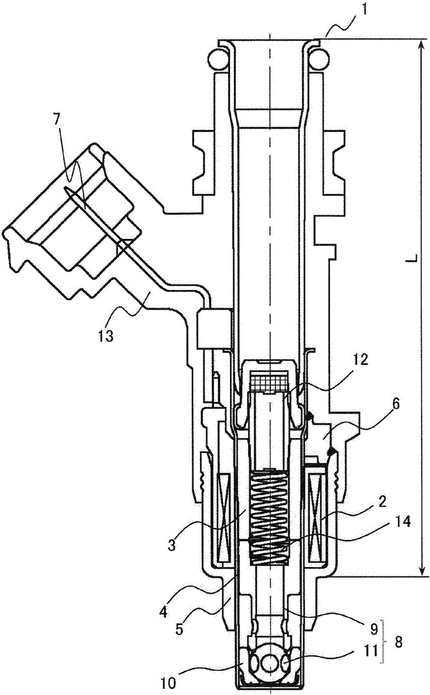
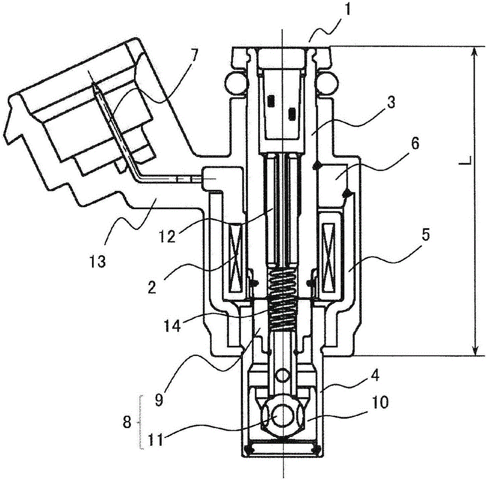
[0049] Next, the fuel injection valve according to Embodiment 1 of the present invention will be described. figure 2 It is a longitudinal sectional view of the fuel injection valve according to Embodiment 1 of the present invention. figure 2Among them, the fuel injection valve 1 includes: a metal casing 5 having an unequal cylindrical shape having a large diameter portion and a small diameter portion; 4. A hollow cylindrical solenoid 2 accommodated inside the large diameter portion of the housing 5; a hollow cylindrical core 3 penetrating the solenoid 2; The armature 9 is held by the bracket 4 so as to be able to move in the axial direction; the valve part 11 fixed to the armature 9; 10. The cover portion 6 that is disposed opposite to the outer peripheral surface of the core 3 and that is in pressure contact with the tapered surface of the opening of the housing 5 is fixed to the housing 5 by welding to cover the opening of the housing 5 in a cap shape; and disposing The ...

Embodiment approach 2

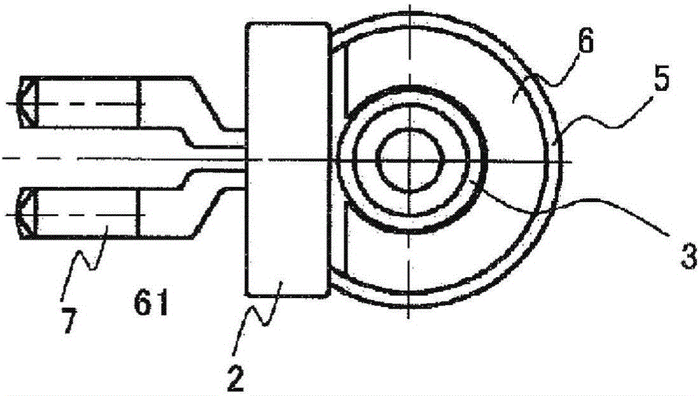
[0062] Next, a method of manufacturing the fuel injection valve according to Embodiment 2 of the present invention will be described. Figure 7 is used to describe one step in the method of manufacturing the fuel injection valve according to Embodiment 2 of the present invention, along Figure 4 Transverse sectional view of line A-A. Figure 7 In this process, the load P is applied by a jig, so that the central axis X2 of the cover part 6 faces the notch 61 of the cover part 6 with respect to the central axis X1 of the core 3 (refer to image 3 ) one side is eccentric until it is in contact with the iron core 3 or is about to contact the state, and the cover part 6 and the iron core 3 are fixed by welding. This step corresponds to the above-mentioned second step. At this time, the load P at which the coaxiality between the core 3 and the bracket 4 does not change is set as an upper limit to prevent poor mold insertion when the connector mold 13 is molded. In addition, since...


PUM


Abstract

A fuel injection valve is provided with: a holder having a core affixed to an axial end thereof; a solenoid received between the inner peripheral surface of a housing and the outer peripheral surface of the core; a cap affixed by welding to both the housing and the core while the solenoid is in the received state; an armature disposed so as to face the axial end of the core and held on the inner peripheral surface of the holder so as to be slidable in the axial direction; a valve section affixed to the armature and capable of sitting on or moving away from a valve seat provided to the holder; a spring for always pressing the armature in the direction in which the armature moves away from the axial end of the core; and an electrode terminal disposed outside the housing and connected to the solenoid. The holder is press-fitted in and affixed to the housing. The cap has a cutout formed by cutting out a part of an annular section, and the inner peripheral surface of the cap is disposed so as to face the outer peripheral surface of the core with a gap therebetween. The electrode terminal is connected to a terminal of the solenoid through the cutout in the cap.

Description

technical field [0001] The present invention mainly relates to a fuel injection valve used in a fuel supply system of an internal combustion engine, and a method of manufacturing the fuel injection valve. Background technique [0002] The conventional fuel injection valve adopts the following structure, that is, the movable valve body forming the valve mechanism is composed of an armature and a valve part. When the valve is opened, the valve body is pressed to the valve seat by a spring. The magnetic field generated by the pipe device will generate a magnetic attraction force that attracts the armature to the iron core side, thereby moving the valve body to the iron core side, thereby creating a gap between the valve part and the valve seat and opening the valve, allowing fuel to flow (for example, Refer to Patent Document 1). [0003] In addition, in the conventional fuel injection valve, the magnetic path is constituted by the iron core, the armature, the bracket, the cas...

Claims


Application Information

Patent Timeline
Patent Type & Authority Applications(China)
IPC IPC(8): F02M51/06
CPCF02M51/0682F02M61/168F02M2200/8046F02M2200/8061F02M2200/8084F02M51/061
Inventor 新宫章男福冨范久平井学宗实毅
Owner MITSUBISHI ELECTRIC CORP
Why Eureka
Try Eureka