Wing structure for wig vehicle

A technology of wing structure and wing-in-ground effect boat, which is applied in the direction of hull, motor vehicle, ship construction, etc., and can solve the problems of undeveloped and increased fuel consumption

Inactive Publication Date: 2011-07-20
WING SHIP TECH CO LTD
View PDF5 Cites 5 Cited by
  • Summary
  • Abstract
  • Description
  • Claims
  • Application Information

AI Technical Summary

Problems solved by technology

Generally speaking, the protrusion is set on the vertical tail of the rear tail of the wing-in-ground effect ship, and a rudder is usually installed. Therefore, when the wing-in-ground effect ship moves, the fuel consumption will increase due to the increase of air resistance.
[0003] However, so far no device has been developed that can replace the vertical tail on WIG boats

Method used


Image

  • Wing structure for wig vehicle
  • Wing structure for wig vehicle
  • Wing structure for wig vehicle

Examples


Embodiment Construction

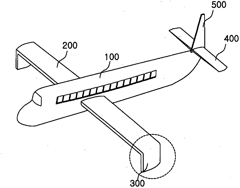
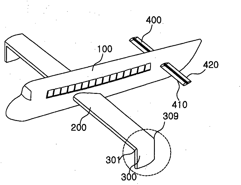
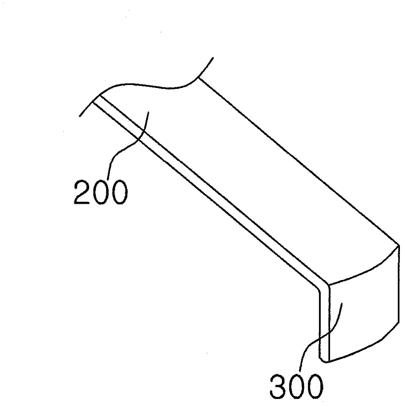
[0036] Below, the wing structure of the WIG craft of the present invention will be described in detail in conjunction with the accompanying drawings.

[0037] figure 1 It is a schematic diagram of the wing structure of the first embodiment of the present invention; figure 2 It is a schematic diagram of the wing structure of the second embodiment of the present invention; image 3 for figure 1 and figure 2 Sectional view of the main wing and downward wing of ; Figure 4 for image 3 Schematic diagram of the interior of the main wing with ribs and spars in ; Figure 5 and Figure 6 It is a schematic diagram of the shape of the lower part of the downward wing; Figure 7 It is a schematic diagram of the wing structure of the third embodiment of the present invention; Figure 8 and Figure 9 for Figure 7 Schematic diagram of the main wing and downward wing structure in ; Figure 10 for Figure 8 and Figure 9 Sectional view of the shape of the lower part of the down...


PUM


Abstract

The present invention relates to a wing structure for a WIG vehicle. More specifically, the wing structure of a WIG vehicle comprises left and right side main wings, left and right downward wings, and a rudder unit. The left and right main wings protrude out from the central portions of left and right sides of the WIG vehicle. The panel of the main wing is flat and tapers successively toward the lateral edge, whereof the cross-section is airfoil-shaped and has the shape of a tadpole. The panel shaped left and right downward wings are connected with both ends of the left and right main wings without a joint and are formed heading downward to suppress vortex and guidance drag generated in both ends of the main wings. The rudder units are mounted on the rear surface of the left and right downward panels with a slight gap in order to compensate asymmetry between left and right lateral ends caused by movement under control of the fuselage driving unit of the WIG vehicle and to turn the fuselage left or right. Therefore, the wing structure of the WIG vehicle is capable of minimizing vortex and guidance drag generated in both ends of the left and right main wings by maximizing ground effect. Additionally, the wing structure has advantages for absorbing impact from the fuselage when taking off and landing and stabilizing horizontal disturbance of the fuselage because the left and right downward wings occupy much more volume than a winglet.

Description

technical field [0001] The present invention relates to a wing structure of a wing-in-ground effect ship, in particular to a wing structure of a wing-in-ground effect ship, which is connected to both ends of the left / right side main wing without joints to form a vertically downward plate, thereby restraining the above two Moreover, according to the control of the WIG hull driving device, the thrust asymmetry between the left and right ends caused by the movement is compensated, so that even in the state of no vertical tail, it can be ensured Bow roll stability of WIG craft. Background technique [0002] Generally speaking, in order to ensure the stability of the bow swing and compensate for the asymmetry of the left and right thrust (Thrust), the aircraft generally use a large vertical tail. This is because it is stipulated in regulations that even if one of the left and right propellers is completely damaged, navigation must be ensured. However, since the wing-in-ground e...

Claims


Application Information

Patent Timeline
Patent Type & Authority Applications(China)
IPC IPC(8): B63B1/16
CPCB64C23/065B64C35/003Y02T50/164B64C39/12B64C5/08B64C23/076Y02T50/10B63B1/16B63B1/18
Inventor 姜昌求李韩镇李昌珉
Owner WING SHIP TECH CO LTD
Why Eureka
Try Eureka