Biological power duplex valve device and charging and discharging method

A bio-based, dynamic fluid technology, applied in heart valve and other directions, can solve the problems of lack of medical equipment and no improvement of cardiac dynamic function, and achieve the effect of low price, convenient portability and good compatibility

Inactive Publication Date: 2011-07-27
于军
View PDF9 Cites 3 Cited by
  • Summary
  • Abstract
  • Description
  • Claims
  • Application Information

AI Technical Summary

Problems solved by technology

Left ventricular annuloplasty, mitral annuloplasty, or bioprosthetic valve replacement can only solve the valve regurgitation problem, but has no effect on improving cardiac power
There is currently a lack of effective medical devices

Method used


Image

  • Biological power duplex valve device and charging and discharging method
  • Biological power duplex valve device and charging and discharging method
  • Biological power duplex valve device and charging and discharging method

Examples


Embodiment 1

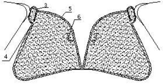
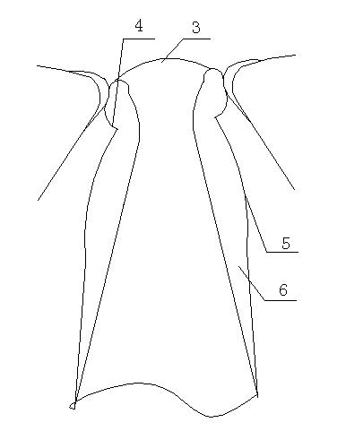
[0021] A biodynamic dual-function valve device, which consists of: a power liquid bag 1, an external pulsation controller 2, and a catheter 3, the power liquid bag 1 is connected to the catheter 3, and the catheter 3 connects the valve ring 4 and a set of support legs 8, the valve ring 4 is connected to the valve leaflet 5, the valve leaflet 5 is connected to the valve liquid bag 6, and the valve ring 4 is connected to the power liquid bag 1, the described The signal sent by the controller of extracorporeal assisting 2 is received by the magnet of the power fluid bag 1 . The valve leaflet has a fluid guide hole and is connected to a power capsule molded by a medical-grade polyurethane material that can recover its shape through a polyurethane material plastic hose.

Embodiment 2

[0023] In the biodynamic dual-function valve device described in Example 1, the valve ring includes a left valve ring, a middle valve ring and a right valve ring, and the valve leaflets include a left valve leaflet, a middle valve leaflet and a right valve leaflet, The valve sac includes a right valve sac, a middle valve sac and a left valve sac.

Embodiment 3

[0025] A liquid filling and discharging method for a biodynamic dual-function valve device. The valve ring of the hollow polyurethane body is connected to the valve liquid bag, and the valve ring plays a triple role of suturing, supporting the valve leaflet and guiding fluid. The valve ring is externally covered with polyester cloth for suturing the valve ring. In use, the left valve liquid sac, the middle valve liquid sac and the right valve liquid sac are filled and discharged. When the valve liquid sac is closed, the liquid is filled and expanded, and when the valve is opened, the liquid is emptied. The surface of the valve liquid sac is covered with bovine heart or pig pericardium. Diaphragm; the power fluid bladder is made of polyurethane material, which is hollow and repositionable. The capsule has a built-in displaceable magnetic body, which can realize the displacement of the magnetic body under the instruction of the external assist controller, and promote the movement ...


PUM


Abstract

The invention relates to a biological power duplex valve device and a charging and discharging method. Dilated cardiomyopathy and ischemic cardiomyopathy are the principal diseases causing congestive heart failure, and have the common pathophysiologic characteristics of atrioventricular valve ring, left ventricular enlargement, atrioventricular valve regurgitation and reduction of ventricular ejection fraction. The biological power duplex valve device comprises a power fluid balloon (1), an in-vitro pump controller (2) and a catheter (3), wherein the power fluid balloon is connected with the catheter, the catheter is connected with a valve ring (4) and a group of holder legs (8), the valve ring is connected with a valve leaflet (5), the valve leaflet is connected with a valve fluid balloon (6), the valve ring is connected with the power fluid balloon, and signals sent by the in-vitro pump controller are received by a magnet of the power fluid balloon. The biological power duplex valve device is applied as a medical appliance.

Description

Technical field: [0001] The invention relates to a bio-type one-way valve-power assisted dual-function valve device at the mitral valve position of the heart, in particular to a bio-type dynamic dual-function valve device and a liquid filling and discharging method. Background technique: [0002] Dilated cardiomyopathy and ischemic cardiomyopathy are the main diseases that form congestive heart failure. The common pathophysiological characteristics are atrioventricular valve ring, left ventricle enlargement, atrioventricular valve regurgitation, and reduced ventricular ejection fraction. Left ventricular annuloplasty, mitral annuloplasty, or bioprosthetic valve replacement can only solve the valve regurgitation problem, but has no effect on improving cardiac power. There is currently a lack of effective medical devices. Invention content: [0003] The purpose of the present invention is to provide a synchronous auxiliary booster actuator for treating failing hearts, which...

Claims


Application Information

Patent Timeline
Patent Type & Authority Applications(China)
IPC IPC(8): A61F2/24
Inventor 于军
Owner 于军
Why Eureka
Try Eureka