Synchronous trenching machine

A technology for slotting machines and submersible motors, which is applied to earth movers/excavators, construction, etc., and can solve problems such as low slotting efficiency, expensive equipment, and complex structures

Inactive Publication Date: 2011-08-03
张永忠
View PDF0 Cites 34 Cited by
  • Summary
  • Abstract
  • Description
  • Claims
  • Application Information

AI Technical Summary

Problems solved by technology

[0002] At present, the trough forming equipment for constructing underground diaphragm walls can be roughly divided into the following trough forming mechanisms: bucket type, impact

Method used


Image

  • Synchronous trenching machine
  • Synchronous trenching machine

Examples


Embodiment Construction

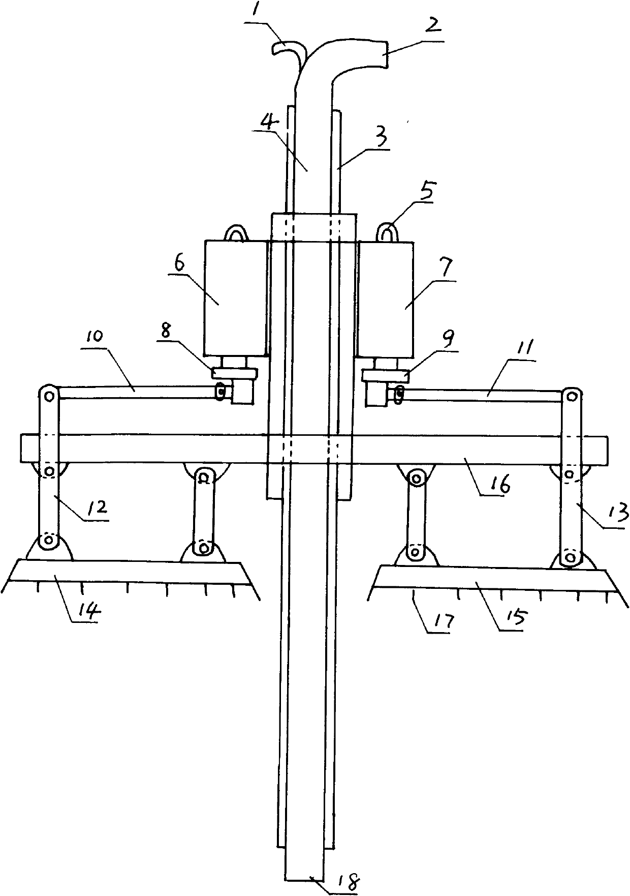
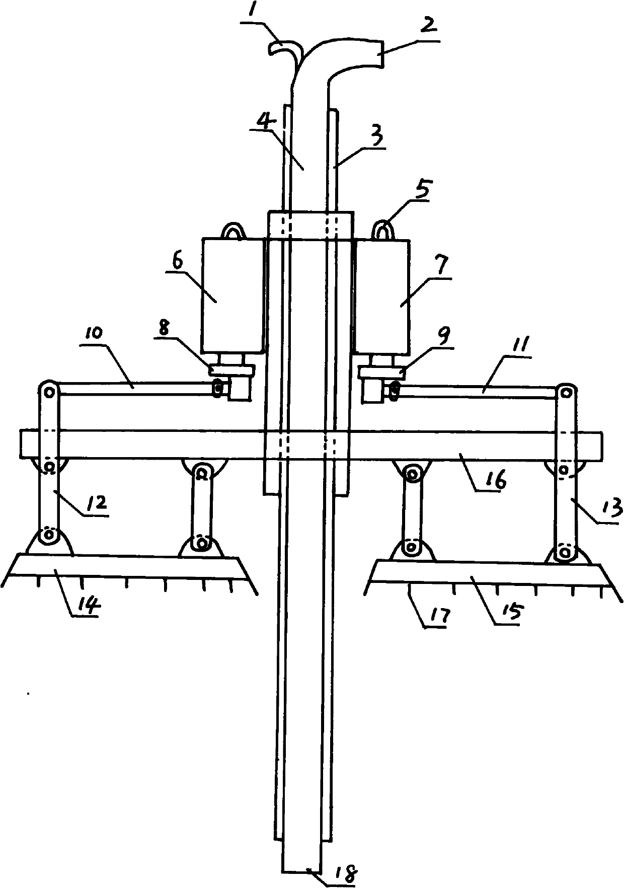
[0009] The accompanying drawing is a specific embodiment of the present invention, which includes a high-pressure air inlet pipe 1, a slurry discharge elbow 2, a slurry discharge steel pipe 4, and two guide rails 3 fixed on both sides of the slurry discharge steel pipe; its special features are: The synchronous submersible motors A6 and B7 are respectively arranged on both sides of the slurry steel pipe 4, and the submersible motor A6 is provided with a crank A8, which is hinged to the upper end of the rocker arm A12 through the connecting rod A10, and its lower end is hinged to the knife arm A14; the submersible motor B7 is provided with Crank B9, crank B9 is hinged on the upper end of rocking arm B13 by connecting rod B11, and its lower end is connected in knife arm B15, and two knife arms are all provided with sharpener 17.

[0010] When the present invention works, the two synchronous submersible motors rotate synchronously, and when the submersible motor A6 drives the cran...


PUM


Abstract

The invention relates to a synchronous trenching machine comprising a high-pressure air inlet pipe, a slurry discharging bent pipe, a slurry outlet steel pipe and two guide rails, wherein the two guide rails are fixed at both sides of the slurry outlet steel pipe. The synchronous trenching machine is characterized in that synchronous submersible motors A and B are respectively arranged at both sides of the slurry outlet steel pipe; a crank A is arranged below the submersible motors A and articulated with the upper end of a rocking arm A through a connecting rod A, and the lower end of the rocking arm A is articulated with a tool arm A; a crank B is arranged below the submersible motor B and articulated with the upper end of a rocking arm B through a connecting rod B, and the lower end of the rocking arm B is articulated with a tool arm B; and the tool arm A and the tool arm B are both provided with cutting tools. The synchronous trenching machine is a special appliance for trenching an underground continuous wall.

Description

1. Technical field [0001] The invention relates to a slotting machine, in particular to a synchronous slotting machine for underground continuous wall slotting. 2. Background technology [0002] At present, the trough-forming equipment for building underground diaphragm walls can be roughly divided into the following trough-forming mechanisms: bucket type, impact type, and rotary type. Although the above-mentioned equipment has its own characteristics, they all have low trough-forming efficiency, expensive equipment, and complex structures. shortcoming. 3. Contents of the invention [0003] The invention provides a synchronous groove forming machine with high efficiency, low cost and simple structure. [0004] The present invention is achieved through the following technical solutions. [0005] A synchronous slotting machine, including a high-pressure inlet pipe, a pulp discharge elbow, a pulp discharge steel pipe, and two guide rails fixed on both sides of the pulp disc...

Claims


Application Information

Patent Timeline
IPC IPC(8): E02F5/02
Inventor 张永忠
Owner 张永忠
Why Eureka
Try Eureka