
Heat treatment production process

A manufacturing process and technology to be heated, applied in semiconductor/solid-state device manufacturing, electrical components, circuits, etc.

Inactive Publication Date: 2011-08-03
UNITED MICROELECTRONICS CORP
View PDF3 Cites 0 Cited by
  • Summary
  • Abstract
  • Description
  • Claims
  • Application Information

AI Technical Summary

Problems solved by technology

[0006] Therefore the object of the present invention is to provide a kind of method that a semiconductor substrate to be heated is carried out heat treatment, to solve the accompanying problem of above-mentioned existing thermal fabrication process
Therefore, the present invention can not only save the trouble of switching different machines during the heat treatment process and shorten the process cycle, but also improve the problem of patterning caused by heating only the front side of the semiconductor substrate.

Method used


Image

  • Heat treatment production process
  • Heat treatment production process
  • Heat treatment production process

Examples


Embodiment Construction

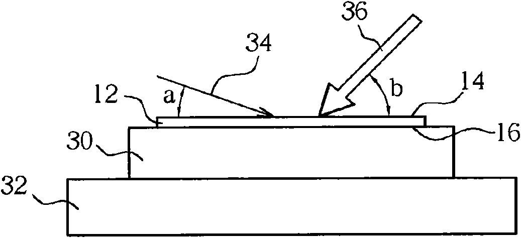
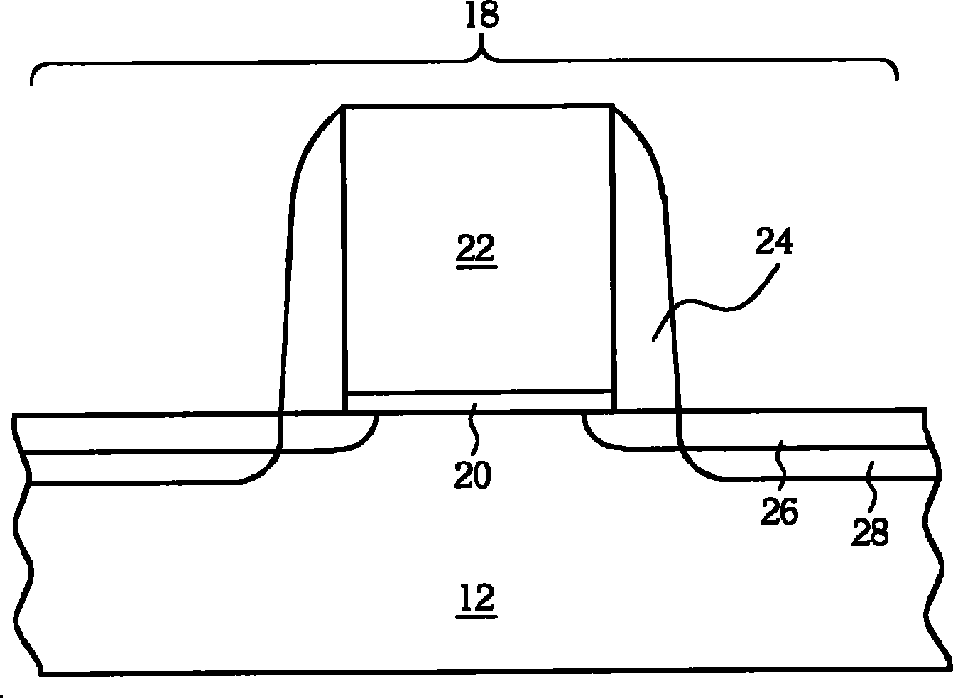
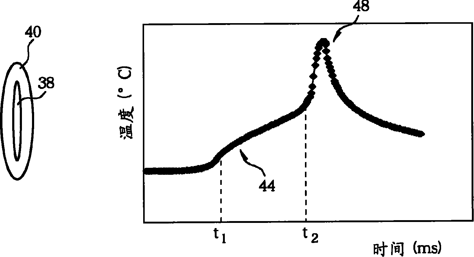
[0033] Please refer to figure 1 and figure 2 , figure 1 It is a schematic diagram of the heat treatment process for a semiconductor substrate to be heated according to the first embodiment of the present invention, figure 2 It is a schematic diagram of a MOS transistor region in the semiconductor substrate. As shown in the figure, firstly, a semiconductor substrate 12 to be heated, such as a silicon wafer, is provided. The semiconductor substrate 12 has a front side 14 and a back side 16 , and a MOS transistor region 18 is defined on the front side 14 . The front surface 14 of the semiconductor substrate 12 of the MOS transistor region 14 is preferably formed with structures such as a gate dielectric layer 20, a gate 22, and a spacer 24, and at least one ion implantation process has been completed, such as a source / drain extension doping process. A doped region (not shown) is in the semiconductor substrate 12 on both sides of the gate 22 or a source / drain doped region (n...


PUM


Abstract

The preferable embodiment of the invention discloses a heat treatment production process, which comprises the following steps of: firstly providing a semiconductor substrate to be heated, and heating the semiconductor substrate by utilizing using at least two first heating light beams and second heating light beams with different energy densities at the same time. Thus, the trouble of needing to switch different machines during the traditional heat treatment production process can be eliminated, the period of the production process is shortened, and the problem of producing a patterned phenomenon due to the heating of the front surface of the semiconductor substrate can be improved.

Description

technical field [0001] The invention relates to a heat treatment manufacturing process, in particular to a manufacturing process for simultaneously heating a semiconductor substrate by using at least two heating beams with different energy densities. Background technique [0002] As semiconductor manufacturing technology becomes more and more sophisticated, integrated circuits have undergone major changes, which has led to a rapid increase in computing performance and storage capacity of computers, and has driven the rapid development of peripheral industries. The semiconductor industry is also developing at the speed of doubling the number of transistors on integrated circuits every 18 months, as predicted by Moore's Law. 90 nanometers (nm) in 2005, entered 65 nanometers in 2005, and moved towards 45 nanometers. Therefore, along with the advancement of semiconductor manufacturing technology and the miniaturization of microelectronic components, the density of semiconductor...

Claims


Application Information

Patent Timeline
IPC IPC(8): H01L21/268H01L21/336
Inventor 杨建伦李静宜郭子凤
Owner UNITED MICROELECTRONICS CORP
Learn More