Elevator system with lightweight glass plates

A glass plate and equipment technology, applied in the field of elevator equipment, can solve the problems of heavy glass components, unsightly connectors, and cost, and achieve the effect of reducing motion energy

Inactive Publication Date: 2011-08-03
INVENTIO AG
View PDF8 Cites 1 Cited by
  • Summary
  • Abstract
  • Description
  • Claims
  • Application Information

AI Technical Summary

Problems solved by technology

In addition, these glass elements are heavy and the application of small holes or drilled holes in the glass panes requires complex and unattractive connections

Method used


Image

  • Elevator system with lightweight glass plates
  • Elevator system with lightweight glass plates
  • Elevator system with lightweight glass plates

Examples


Embodiment Construction

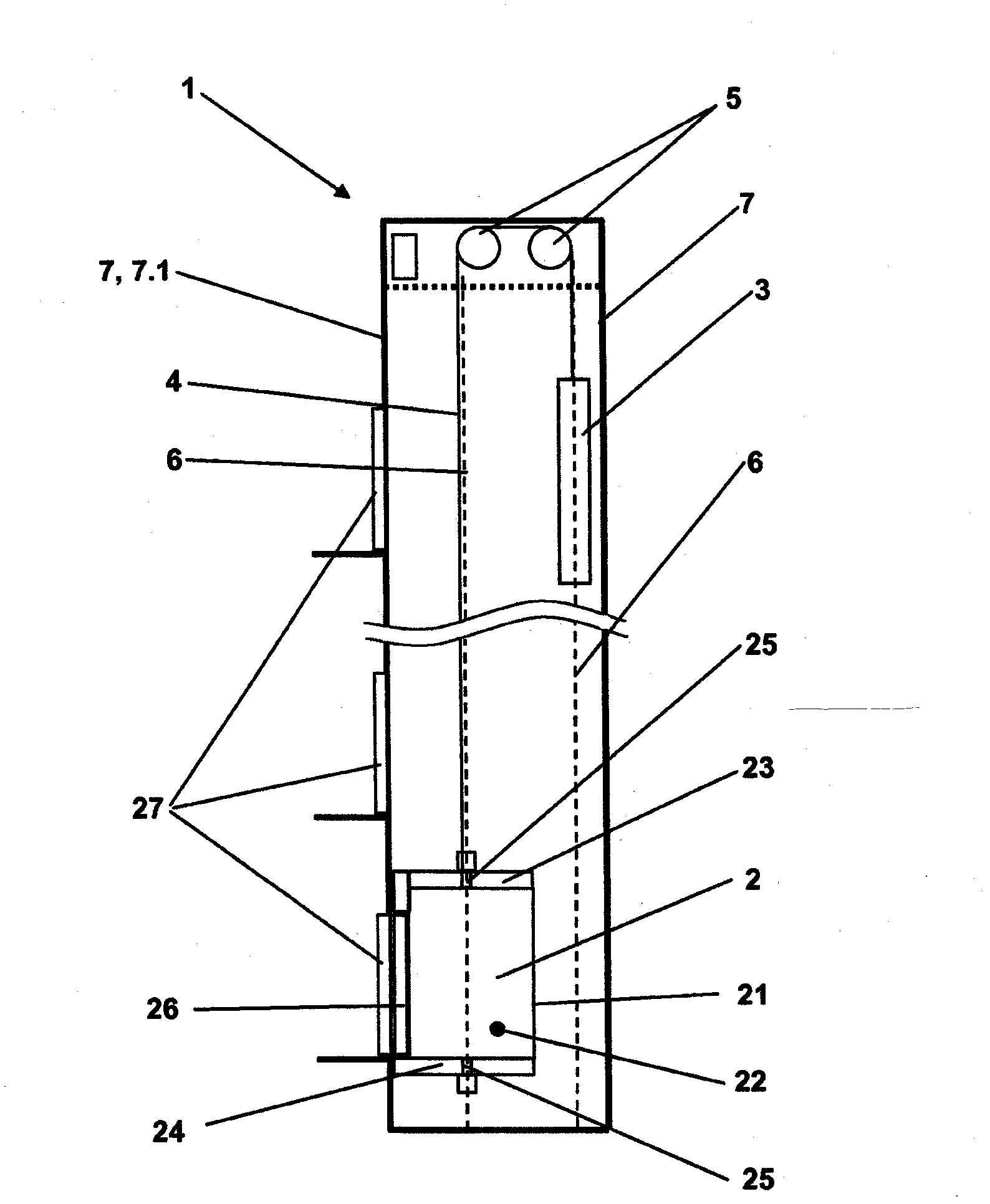
[0052] figure 1 A possible general structure diagram of an elevator is shown in . The elevator 1 or elevator system comprises at least one elevator car 2 , a drive 5 , a counterweight 3 and also a support device 4 . The drive device 5 drives the support device 4 and thus moves the elevator car 2 and counterweight 3 in the opposite direction. The car 2 is designed to accommodate people and / or goods and to transport it between floors of a building. The car 2 and the counterweight 3 are guided by means of guides 6 . The elevator is built in a shaft, wherein the shaft is essentially defined by the travel space, which itself is defined by the travel path of the car 2 and the counterweight 3 . It contains safe spaces and spacing in all cases.

[0053] The shaft is delimited by shaft walls 7 . The shaft wall 7 can optionally be produced partly or completely from the lightweight glass panes according to the invention, from other building materials or from a mixture of any desired...


PUM

PropertyMeasurementUnit
thicknessaaaaaaaaaa
thicknessaaaaaaaaaa
thicknessaaaaaaaaaa

Abstract

The invention relates to a lightweight glass plate comprising a first glass plate (12), a second glass plate (11) and an intermediate layer (13) that connects the first and the second plates together. The lightweight glass plate further comprises at least one connection element (18) that allows the lightweight glass plate to be connected to an abutting component. The connection element is embedded into the intermediate layer (13) in an edge area of the lightweight glass plate and the intermediate layer extends to surfaces located between the connection element and the glass plates. The lightweight glass plate is preferably used in the preparation of elevator doors and/or cabin walls. The lightweight glass plates are lightweight and can transfer large forces.

Description

technical field [0001] The invention relates to an elevator installation with a glass structure according to the preambles of the independent claims. Background technique [0002] The elevator equipment is mainly composed of a car, which is connected with a counterweight through a carrying device. The car is moved along a substantially vertical car track along the front wall of the shaft by means of a drive which acts optionally on the carrier, directly on the car or on the counterweight. The car running track is usually integrated in the shaft of the building. The shaft is delimited by at least one shaft front wall, by further shaft walls, the shaft ceiling and the shaft floor. The shaft front wall and possibly further shaft walls have openings through which the shaft or a car arranged in the shaft can be accessed. These shaft openings can be closed by means of shaft doors. The car itself has car doors which occasionally cooperate with shaft doors to open or close acces...

Claims


Application Information

Patent Timeline
Patent Type & Authority Applications(China)
IPC IPC(8): B66B13/30B32B17/10
CPCB32B17/10302B32B17/10036B66B13/303B32B17/10293E06B3/4681B66B11/0253B66B13/30B66B11/02B32B17/10045B32B17/10247
Inventor 安德烈亚斯·弗里德格尔特·西尔伯霍恩米夏埃尔·盖斯胡斯勒尼古拉斯·格雷芒德
Owner INVENTIO AG
Why Eureka
Try Eureka