Rotating hydraulic system of crane and rotating buffer valve thereof

A technology of slewing buffer and back pressure valve, which is applied in the field of slewing buffer valve and crane slewing hydraulic system, which can solve the problems of unsatisfactory slewing system stability, large slewing moment of inertia, and insufficient stability.

Active Publication Date: 2011-08-17
XUZHOU HEAVY MASCH CO LTD
View PDF4 Cites 33 Cited by
  • Summary
  • Abstract
  • Description
  • Claims
  • Application Information

AI Technical Summary

Problems solved by technology

[0006] The slewing buffer valve is composed of a check valve and an electric proportional pressure reducing valve 50, which has insufficient stability at the moment of s...

Method used


Image

  • Rotating hydraulic system of crane and rotating buffer valve thereof
  • Rotating hydraulic system of crane and rotating buffer valve thereof
  • Rotating hydraulic system of crane and rotating buffer valve thereof

Examples


Embodiment Construction

[0029] The core of the present invention is to provide a rotary buffer valve, which can make the rotary have better stability and can improve the rotary efficiency. Another core of the present invention is to provide a crane slewing hydraulic system including the above-mentioned slewing buffer valve.

[0030] In order to enable those skilled in the art to better understand the technical solutions of the present invention, the present invention will be further described in detail below in conjunction with the accompanying drawings and specific embodiments.

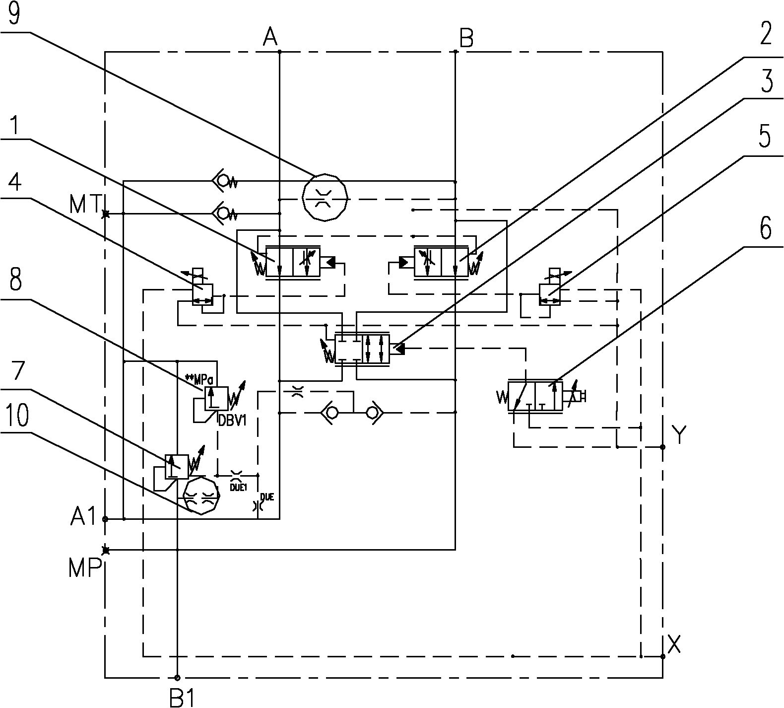
[0031] Please refer to figure 2 , figure 2 It is a hydraulic schematic diagram of a specific embodiment of the rotary buffer valve provided by the present invention.

[0032] The valve body of the rotary buffer valve in this specific embodiment has a first oil port B1, a second oil port A1, a third oil port A and a fourth oil port B, and the third oil port A and the fourth oil port B are connected to the The oil port o...


PUM


Abstract

The invention discloses a rotating buffer valve which comprises a first back pressure valve, a second back pressure valve and a buffer reversing valve, at the moment of the start and stop of the rotation, hydraulic oil only can enter a rotating motor through a passageway which is provided with the back pressure valve, and then flows to an oil tank; and when in a steady rotating process, the hydraulic oil enters the rotating motor from the buffer reversing valve, then flows back the buffer reversing valve from the rotating motor, and further flows back an oil back tank. At the moment of the start and stop of the rotation, the hydraulic oil only can flow from the first back pressure valve and the second back pressure valve, thus the flow rate and pressure of the hydraulic oil can be controlled effectively, instant system high pressure caused by the instant start and stop of the rotation can be eliminated, the stability of rotation can be improved, and the aim of buffer can be achieved; and during the rotating process, the hydraulic oil can directly enter the rotating motor to work from the buffer reversing valve, thus the rotating efficiency can be improved. The invention also provides a rotating hydraulic system of a crane of the rotating buffer valve.

Description

technical field [0001] The invention relates to the technical field of engineering machinery, in particular to a rotary buffer valve. The present invention also relates to a crane slewing hydraulic system comprising the above-mentioned slewing buffer valve. Background technique [0002] With the continuous development of the construction machinery industry, the lifting weight and lifting height of the crane are gradually increasing, and the performance is gradually improving. [0003] Taking wheeled cranes as an example, for wheeled cranes with large and medium tonnages, the booms are long and the weight is heavy. When the vehicle is slewing, the slewing moment of inertia is large, resulting in poor slewing performance. If closed pump control hydraulic pressure is adopted The system controls the slewing of the whole vehicle, so the system has better micro-movement and comfort, but the cost is relatively high, especially for medium-tonnage wheeled cranes, the use of a closed...

Claims


Application Information

Patent Timeline
IPC IPC(8): B66C23/86F15B13/02
Inventor 史先信刘邦才王必旺张党辉游焕强
Owner XUZHOU HEAVY MASCH CO LTD
Why Eureka
Try Eureka