Insulated gate bipolar transistor (IGBT) short circuit protection circuit and control method

A short-circuit protection circuit and control method technology, which is applied in emergency protection circuit devices, protections that respond to overcurrent, electrical components, etc., can solve problems such as unreliable protection, and achieve short-circuit protection, simple and reliable circuits.

Active Publication Date: 2011-08-17
EURA DRIVES ELECTRIC
View PDF10 Cites 14 Cited by
  • Summary
  • Abstract
  • Description
  • Claims
  • Application Information

AI Technical Summary

Problems solved by technology

[0003] The purpose of the present invention is to provide a short-circuit protection circuit for IGBT to s

Method used


Image

  • Insulated gate bipolar transistor (IGBT) short circuit protection circuit and control method
  • Insulated gate bipolar transistor (IGBT) short circuit protection circuit and control method
  • Insulated gate bipolar transistor (IGBT) short circuit protection circuit and control method

Examples


Embodiment Construction

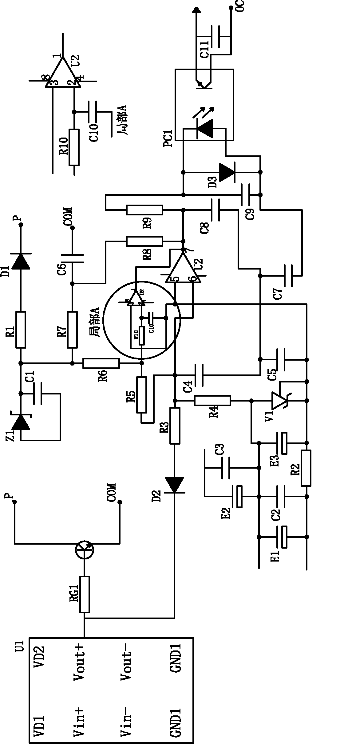
[0013] Specific embodiments of the present invention such as image 3 As shown, the IGBT optocoupler driver module U1 uses HCPL3120, the diode D1 uses the fast recovery high voltage diode SF1600, the comparator U2 uses LM393, the diode D2 uses 1N4148, and the photocoupler PC1 uses PS2701. The function of diode D1 is the same as that of diode D01, the function of diode D2 is the same as that of diode D02, the function of voltage dividing resistors R4, R5, R6 is the same as that of resistors R04, R05, R06, and the function of comparator U2 is the same as that of comparator U01.

[0014] In this embodiment, the IGBT short circuit protection circuit includes resistor RG1, resistor R1, resistor R2, resistor R3, resistor R7, resistor R8, resistor R9, capacitor C1, capacitor C2, capacitor C3, capacitor C4, capacitor C5, capacitor C6, Capacitor C7, capacitor C8, capacitor C9, diode D3, voltage regulator tube V1, voltage regulator tube Z1, capacitor E1, capacitor E2, capacitor E3, the ...


PUM


Abstract

The invention discloses an insulated gate bipolar transistor (IGBT) short circuit protection circuit and a control method thereof. The circuit comprises a comparator, a photoelectric coupler and a signal delay circuit. The invention aims to provide an IGBT short circuit protection device with a simple structure and low cost.

Description

technical field [0001] The invention relates to a short-circuit protection circuit and a control method, in particular to a circuit and a control method for realizing IGBT short-circuit protection. Background technique [0002] At present, IGBT (Insulated Gate Bipolar Transistor) is widely used as a high-power switching device, but the protection of IGBT has always been a difficult point. The general IGBT drive protection module is to monitor whether Vce is greater than the saturation voltage drop. To achieve IGBT overcurrent protection, one of the widely used solutions is to use Ximenkang and Mitsubishi’s drive protection modules, but the cost of this solution is too high, especially for low-power models; The circuit detects the output current to realize protection, but this scheme cannot directly detect the current of each IGBT, and cannot realize short-circuit protection completely and reliably. Contents of the invention [0003] The purpose of the present invention is...

Claims


Application Information

Patent Timeline
IPC IPC(8): H02H7/20H02H3/08
Inventor 林海光杨高孟
Owner EURA DRIVES ELECTRIC
Why Eureka
Try Eureka